Monday, 9 May 2011

Bowden extruder configuration and final mechanical assembly

I have now reached the point of axis testing and calibration, all the mechanics are now working and hopefully apart from a bit of oil and adjustments I should have ScrewBallStrap running in the next few days.

This is the machine with the Full size build-bed, about 330mm x 480mm
I'm going to only use half of it for initial testing, this is easy as I just slide out one end and change the 20mm x 20mm supports to be smaller.

This will be the smaller build bed for testing the machine (slightly over A4 sized)

I have mounted the Bowden extruder on the underside of the electronics at an angle so I can keep the PTFE delivery tube as short as possible to the hot-end.

Side view makes it a little easier to understand - 
E = Electronics Box.
A = The Rubber isolation points, these provide vibration isolation and also allow the platform (B) to be angled.
B = 12mm Polycarb base.
C = Is the point where the filament enters the Extruder from the back of the machine.
D = The filament exits the extruder inside the PTFE deliver tube.

A back view of the same assembly.

More testing later and some updates to follow, it's getting close to printing now.

Rich.

Sunday, 8 May 2011

Finished wiring

Everything is wired up and testing has started.
I'm still using the official 5D with a Mega at the moment, but I'm going to try out some other firmwares with this build as soon as I know it's all operational.

Boxed up wiring.

Pololu Stepper drivers added with small blue heatsinks added

Testing X first.

Opto's tested and all working


Fan added to cool stepper drivers.

And finally the extruder hot-end all wired up and working. Note the red LED so I can tell when power is being applied to the heater block.


Saturday, 7 May 2011

Wiring Screwball strap and electronics install

I have been adding the electronics and wiring to my 2nd Repstrap (Screwballstrap).
As it uses aluminium t-slot, you can route the wiring inside the frame and use some plastic channel to make it all nice and neat.
Frame wiring - t-slot 30x30

Opto wiring Z Axis

Opto wiring Y Axis

A Polycarbonate box will house all the electronics (RAMPS+) and flexi-wire fittings will allow all control cable and power access.


Almost all wired up, now for testing the electronics.

More updates soon.
Rich.


Thursday, 17 March 2011

Hot-end for 1.75mm Filament (Push-fit Bowden)

My new push-fit 1.75mm Hot end is finished, it's based on similar designs like Adrian's new micro hot-end -

Here is how I made it -

I am a big fan of using off-the-shelf parts where possible in Reprapping, so using Pneumatic Push-fit connectors was an obvious choice for attaching the PTFE (bowden) tube to my extruder assembly.
The other standard part I always try to use is the metal rail mounts shown above. They work well as a clamp and  are low cost (£2 / $3) and easy to modify.
This 8mm mount above is manually tapped so I can screw in the Push-fit (1/8")

I'm using a simple Aluminium R/A piece to mount to my Repstrap, you could use something different to mount to Mendel, Prusa or Rapman machines.
10mm PEEK rod and block, 1.75mm Hot-end with 0.35mm Nozzle.

Turn down both ends of the PEEK rod (one 7.2mm and the other 8mm).
Then with a 4mm drill bore the barrel - the PEEK will expand and shrink so the hole will be undersized, but that's good.

Cut a length of 4mm (outer) PTFE tube.

Then you need to push the PTFE tube into the PEEK barrel, this is hard so taper the tube end with a pencil sharpener and force it in, you may need some PTFE spray to help this process.

Cut down the tube but make sure to allow both ends of the tube to compress slightly, one in the push-fit end and the other in the hot-end, you can tighten down the push-fit after it's all at temperature as the PTFE tube will elongate with temperature, you don't want any leaks.

Drill your PEEK block so it has the same spacing as the rail mount.

Drill your chosen mounting bracket.

Assemble with 55mm M4 bolts, washers and nuts, you can use a Nyloc nut at the top, it should not get hot enough to melt them.

You will need to tighten everything after it gets up to temperature for the first time, the PEEK will bend.

The other end of the PTFE tube is connected via a push-fit on the Extruder, so the 1.75mm filament can be driven down the tube to the hot-end.

I hope to have some examples of it running soon, I now have the last remaining Pololu stepper drivers, so I can start to wire-up the ScrewBall strap and get back to 3D printing (another 3D printer) !

Rich.

Sunday, 13 March 2011

Bowden Extruder - DIY RepStrap build for 1.75mm or 3mm Filament.

So for my new Repstrap (ScrewBall Strap) I am going to be using both 1.75mm and 3mm Filament, with a dual extruder set-up (eventually).
I wanted a bomb-proof extruder so I can print fast and reliably, so I hand-made one. That's the plan anyway...

I will of course print one of Adrian's new Mini extruder's and have a go at using a NEMA11 motor in a Bowden configuration at some point, but for now here is how this one was made and assembled.

Top shows the filament drive path and Pneumatic Push-fit connector for standard 4mm or 6mm PTFE tube.
Middle is Idler bearing block.
Bottom right is Nema17 motor mount.

Close up of Pneumatic connector - tapped and screwed, PTFE tube can easily be fitted and removed.

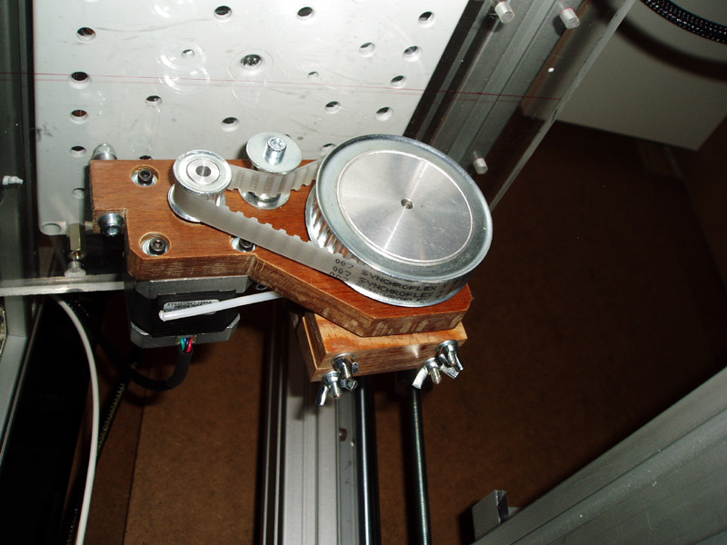
 I decided on a 10mm belt-driven drive-train (belt is 280mm) Pulley's are 16 and 40 teeth.

I wanted a straight-through filament drive so it's easily mounted on my RepStrap and could be made to tilt as printed build-height increases.

Underside - Excessive use of bearings for a belt-tensioner I know.

I mounted the 4 springs recessed inside the bottom block, so I can just use normal wing-nuts on the top idler block, this makes it much easier to take apart to clean and reduces the total height by using dead space for the springs inside the extruder body instead of sticking out the top.

This has 3mm ABS coming out of the 6mm Push-fit Pneumatic connector, but it's just as easy to screw in a 4mm for 1.75mm Filament drive.

I'm sure this design could easily be printed so If it all works well I will try to print a copy of itself and post some design files. And I really like the Herringbone Gears, so I expect that will replace the belt-drive in a printed model.

I also think the internal compression springs idea could be incorporated into other extruder designs, it really makes filament change and cleaning a much easier job than having to remove the springs each time.

I have also made a new 1.75mm hot-end for this Bowden driven Extruder, I'll post that and how I made it tomorrow.

Rich.

Saturday, 12 March 2011

RAMPS+ DIY build completed

I have finished building my RAMPS+ board, apart from the last few Pololu Stepper carriers as they are still out of stock in the UK. :(
But by 18th march they should start to ship out more Pololu steppers to people, so hopefully I can test it fully around then.

And while I waited for those I have just finished my first Bowden Extruder with a 1.75mm filament drive and my own design of a push-fit style hot-end, photo's and more on that tomorrow.

Rich.

Tuesday, 8 March 2011

RAMPS+ Electronics Build up

I printed (Toner Transfer) another RAMPS+ PCB, this time with standard FR4 material, 1oz Copper.

It came out perfectly, so I drilled it and started the assembly -

The RAMPS Wiki page is missing a good Component Ident (silk screen), if I get time I will upload one, so it's hard to see what parts I have fitted, but as with all DIY PCB assembly, you should try to start with the lowest components first and fit the tallest ones last.

Single sided RAMPS boards need a few wire links on the top, some in blue here.
the 6way 0.1" headers select the Stepping mode for the Pololu carrier boards.

I'm using Screw down terminals for motor and Mosfet outputs.
The RAMPS layout does not really provide much room for slightly chunkier components, I will give everything much more room on the PCB when I layout my new electronics design.

About  80% completed. I'm not going to fit the 2nd and 3rd extruder positions at the moment.

And talking of Extruders I was inspired by Adrian's micro extruder so I had a push on to finish the hardware for my first Bowden extruder. It will be able to swap from 3mm to 1.75mm Filament easily. And then I plan to print a dual extruder version if the hand-made one works out and the Bowden cable operation is ok - 
more on that in the next Blog post.

Rich.