The E3D #ToolChanger - Part 2
Hello everyone, In part 1 I introduced the concept of a ToolChanger as a 3D printer. In this post, I'm going to be building up the E3D Beta30 reference kit.
In part 3 we will be looking at how to setup ToolChange scripting and the RepRap firmware on the Duet 2 electronics. (And doing some actual 3D printing).
In part 3 we will be looking at how to setup ToolChange scripting and the RepRap firmware on the Duet 2 electronics. (And doing some actual 3D printing).
Quick Jump Index
I'll update this list as I post more blogs and video's about the ToolChanger adventures.
- Part 1 - First ToolChanger Post - Introduction and un-boxing.
- Part 2 (This post) - Motion System Assembly, electronics wiring and building tool heads.
- Next post - Firmware and Duet 2 setup - Scripting and ToolChange processing.

This is what we are aiming for when complete - Wiring (image above) and completed assembly with tool heads (image below) -

This blog
post will cover the assembly and wiring of the ToolChanger.
Assembly
documentation for the Beta30 machines was produced by Greg at E3D,
this consisted of five separate documents for the various stages of
the assembly and wiring.
I will
loosely follow the five different sections as it also makes sense to
focus on these areas when showing how the ToolChanger has been
designed.
1 - Motion
System Assembly
2 -
Tool-Changer Assembly
3 - V6
Dock Assembly
4 - V6
Bowden Tool Assembly
5 - Motion
System Electronics
Motion System -
I followed
them in the above order, you can do them in almost any order you
like, but it's well worth reading all of the documentation first
before you begin any assembly.

You will
need to gather tools, some materials (like metal banding) and other
fixings, super glue and a bunch of other things.
Firstly if
you build up a machine like this, be aware you probably need to buy
some thread-lock fluid. Many steps are using metal parts, nuts and
bolts that require a smear of thread-lock to stop them coming loose
in use. Don't skip this advice, it's going to save you a lot of
trouble down the road when you have your machine running.
Quite a few different things need to be thread-locked, so it's well worth trying to do as much as possible all at the same time. You need to leave 8+ hours for the thread-lock to set, so it's highly frustrating to complete some steps, then wait and then find you need to do more and have to wait again before you can finish the assembly. Give yourself a few days to complete the assembly, and another day at least to do the wiring.


You do get (almost) all the fixings you need to build up the ToolChanger - some (like 50mm M3 bolts) need to be sourced yourself, and a few E3D have already decided to add into the next round of kits to make it easier for people.

The frame construction is easy, you just bolt four vertical 30mm x 60mm aluminium extrusions - one in each corner to the base sheet of 4mm aluminium plate.
 The back acrylic sheet is supplied - and E3D are considering also supplying the side panels in future ToolChanger Kits as they add a lot of strength and rigidity to the machine when built. Most of the Beta30 testers needed to get their own side panels cut locally. I was very kindly sent a set by Greg cut by E3D.


Fix on the back acrylic sheet - all the electronics, extruder motors and wiring mount onto that.

The motion system plate can be mounted on top of the four vertical extrusions, and bolted down - not to tightly at this point.

The Z axis module is next to be fitted - in between the top and bottom aluminium plates.


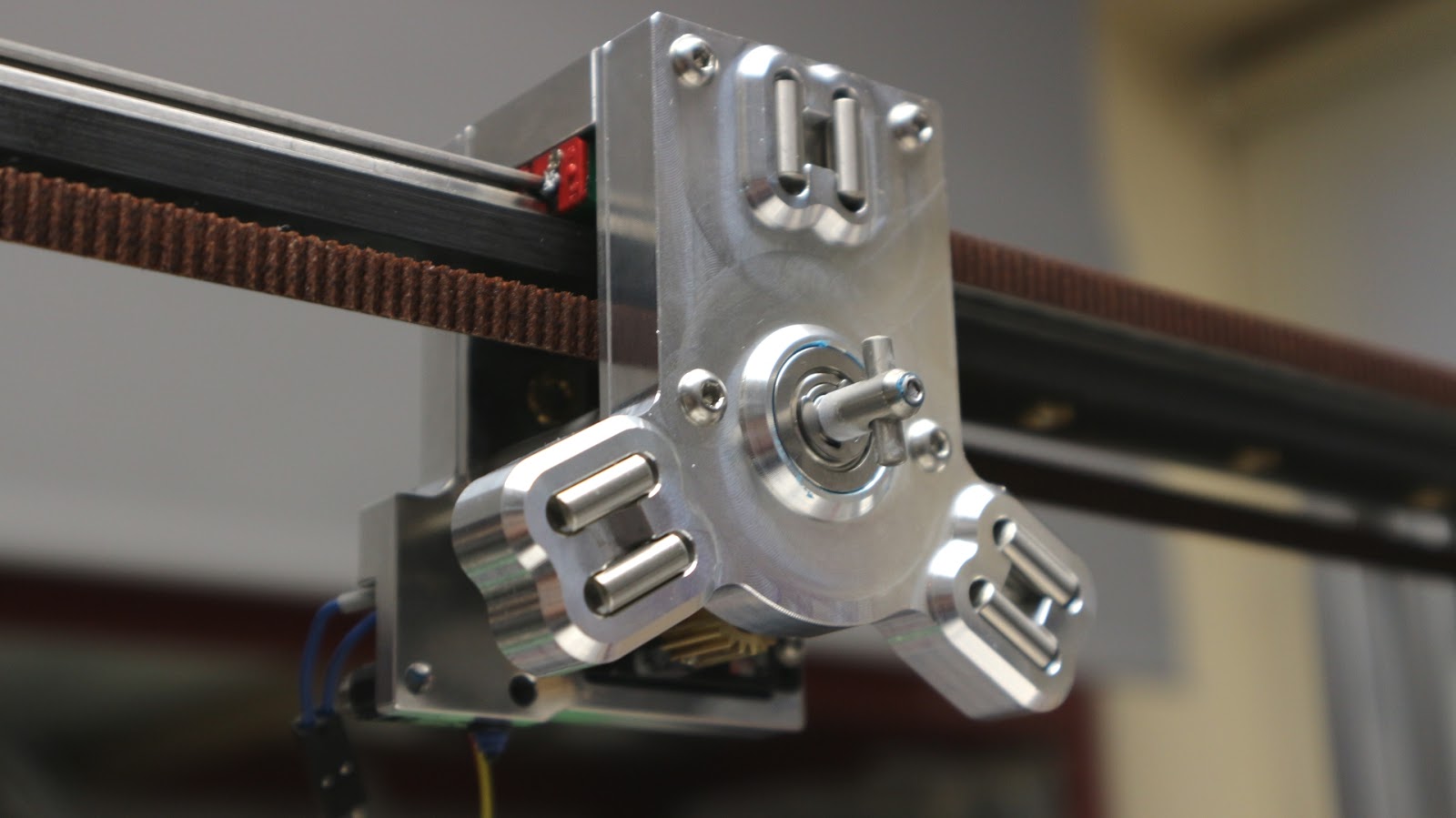
Next to be assembled was the main tool dock for the ToolChanger X/Y carriage -

The tool head consists of a Z-probe switch, high quality (metal geared) micro-servo and a rotating rod with locking pin to clamp down (as it rotates) gripping a tool on the kinematic coupling plate (far right plate in the picture above).

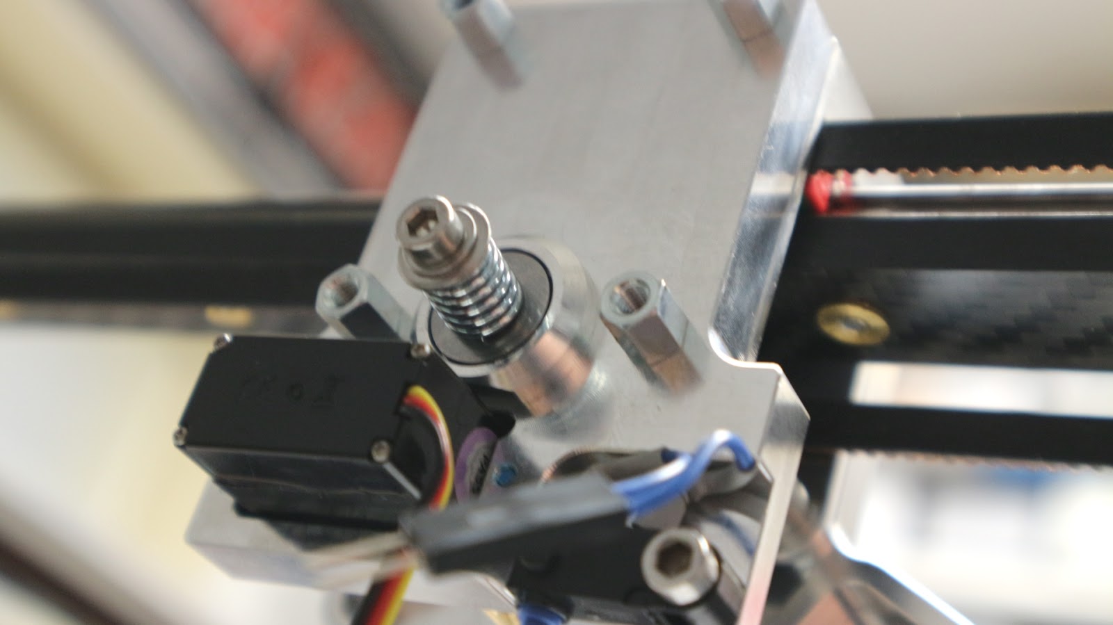
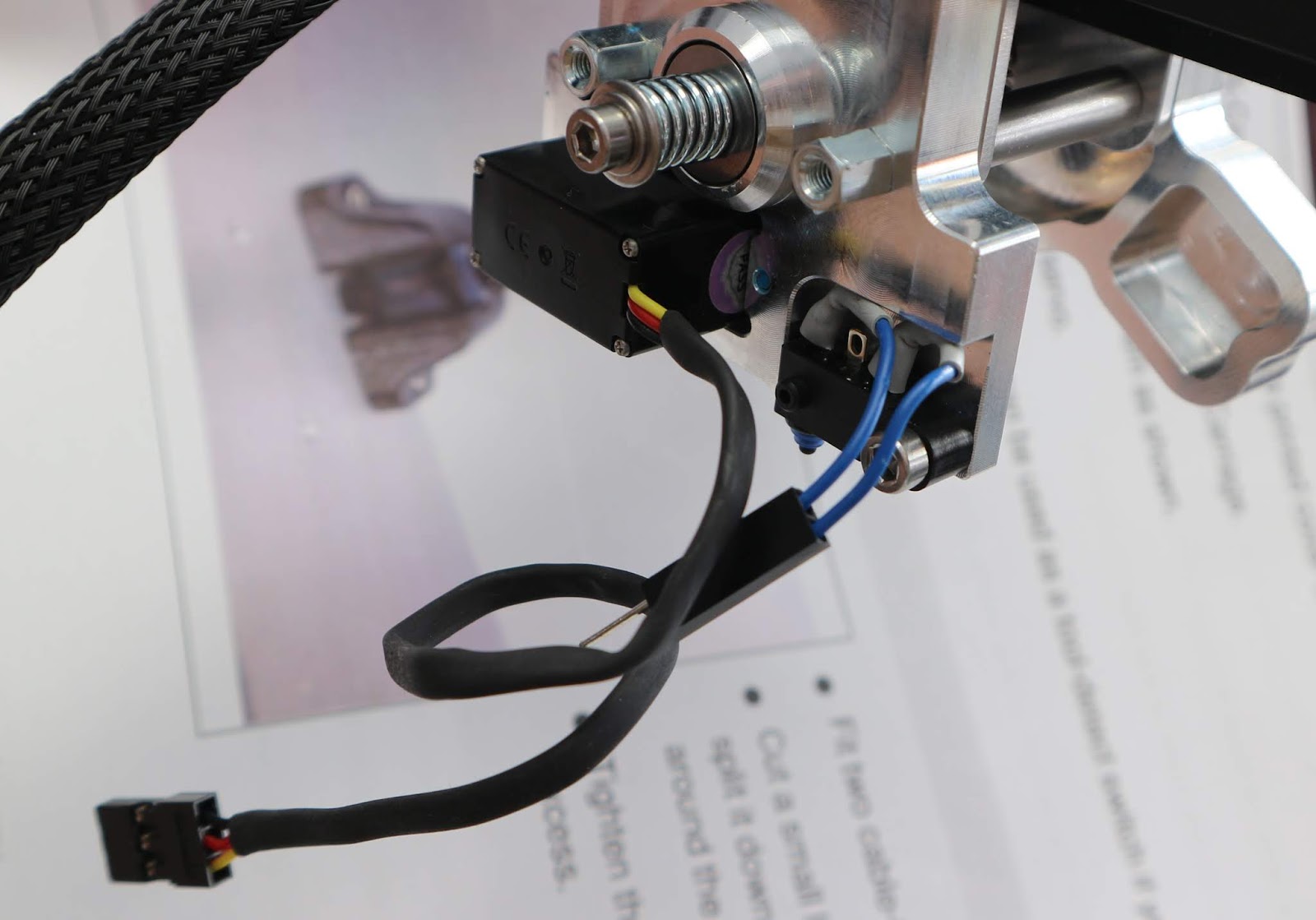

Before adding the cover, I also routed the cables and wrapped the servo wires to the servo body with kapton tape.

A simple printed safety cover fits on the the back to hide the wiring and cable entry point.
V6 Dock Assembly -
The tool docks are fitted on to the back of the machine, they hold the tool ready for a pick-up by the tool head we just assembled above.

Not too many parts for this section - just a matter of following the assembly instructions - easy.

That's it.
The tool assembly is a little more involved, and for the initial machine setup I'm using 4 x E3D V6 hot-ends - Configured in a bowden Titan arrangement.


Each tool head has a small PCB (that may not be the case in future ToolChanger kits - so do check).

You are then just building up V6 hot-ends and adding them onto the supplied coupling plate (fitted with 8mm steel ball bearings)


The tools just slide on to the docks we assembled in the previous section, and can be connected up up to the Titan extruders with a length of 4mm PTFE tube and wiring to the duet motor drives.

The Titan extruders are easy to build - just be aware you need 2 x normal and 2 x mirrored Titan's for the ToolChanger. (1.75mm - were used in this machine)

Another thing to be aware of is that the acrylic back panel is 5mm thick, so all Titan screws need to be +5mm longer to reach the NEMA17 motor holes.


Do them all at once, and I always put a drop of superglue on to my gears and the grub-screw to keep things securely fixed.

Check the fit (before you superglue !) and then mount on the acrylic back panel.

Motion System Electronics -
The final area of assembly and wiring are the electronics and connecting cables.
This is probably the most tricky part for most people. But take your time and check everything at least twice.

The Duet2electronics have a lot of different options, so not all the decisions
below need to be followed, it will depend on how you want your
machine to be configured, these are the choices I made -

I'm using PT100 temperature sensors (instead of thermistors or thermo-couples). To use PT100 temperature sensors on the Duet 2 you need two daughter boards that expand the temperature sensing capability to four channels of PT100 thermal amplification. These are simple to install, but a little tricky to wire to the supplied screw-terminal connections.
The PT100 sensors allow higher temperatures than the normal glass bead thermistors usually fitted to V6 hot-ends.
I used just two of the four wires for the connection to the daughter-boards. Leaving all four of the 0.1” option jumpers in place.
 It's not immediately obvious how to wire up the PT100 sensors to the Duet PT100 daughter-boards, but just as before, follow the extra instructions on the Duet3D website and you will quickly see how to wire up either 4 wire or 2 wire types.
 They mount on the Duet 2 (above) and Duex5 (below) easily, and you can stack another set to get even more channels of PT100 (or Thermocouple) sensing on the Duet electronics.


I'm using PT100 temperature sensors (instead of thermistors or thermo-couples). To use PT100 temperature sensors on the Duet 2 you need two daughter boards that expand the temperature sensing capability to four channels of PT100 thermal amplification. These are simple to install, but a little tricky to wire to the supplied screw-terminal connections.
The PT100 sensors allow higher temperatures than the normal glass bead thermistors usually fitted to V6 hot-ends.
I used just two of the four wires for the connection to the daughter-boards. Leaving all four of the 0.1” option jumpers in place.


You can
wire these differently for different types of PT100 sensor and also
if you remove the option jumpers – As always check the latest
advice from the manufacturer as you may have a different revision of
a PCB or assembly – Duet Documentation is really good, do check itout here -
 The Duet2 and the Duex5 expansion are fitted to the back of the acrylic panel - then you can start wiring.
 You get a big coil of ready-made cables for the ToolChanger, most just need to be connected to the right connection on the electronics, a few need to be screwed or cut.

Following the instructions for connection, it does not take long to get the tool-heads connected up.

After most of the cable are connected to a tool, carriage or motor, you will end up with cables hanging down the back of your machine.


 You can then start routing them nicely along the back, and zip-tie as required.
 The next job is to mount the power supply.
 And fix the solid state relay - if you are using the mains powered heated bed option (it's amazing).

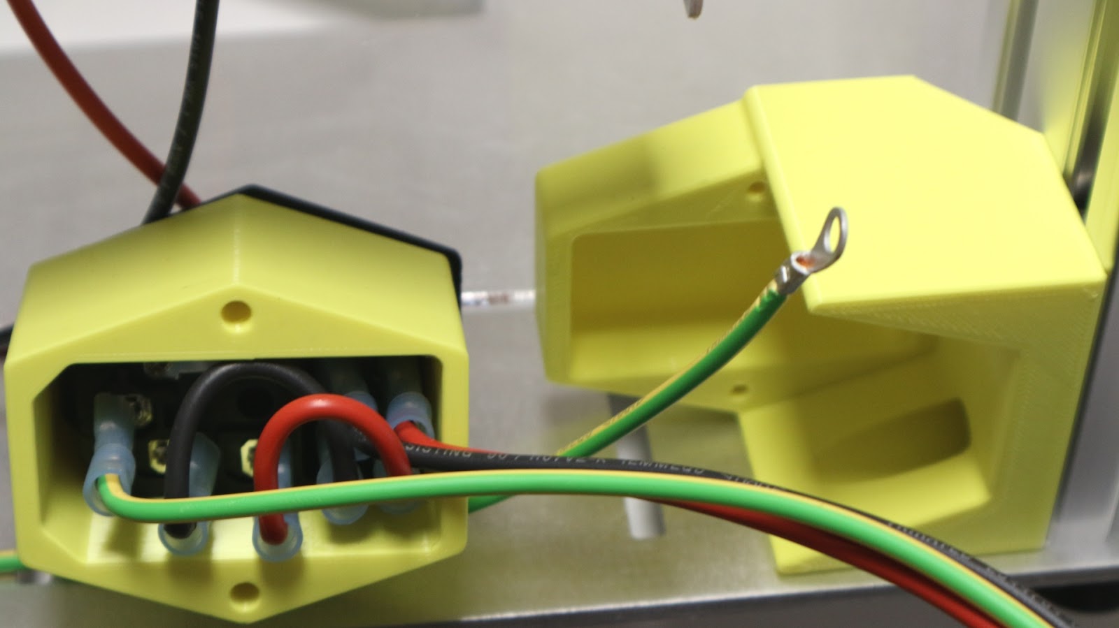
A little bit of mains wiring is required, so take your time and check everything twice.


And make sure everything it correctly earthed.


If you are using the mains powered heated bed - do make really sure you have a good earth connection the the metal plate.


Following the instructions for connection, it does not take long to get the tool-heads connected up.

After most of the cable are connected to a tool, carriage or motor, you will end up with cables hanging down the back of your machine.


A little bit of mains wiring is required, so take your time and check everything twice.
Then you need to fit the heated bed.


If you are using the mains powered heated bed - do make really sure you have a good earth connection the the metal plate.
If in doubt - check with the latest wiring diagrams available at the time - I used the above as a useful guide for the Beta 30 kits.

After a lot more checking - double-checking and a a night of sleep - I decided to turn it on the the first time... And yes! it powered up.
I'll finish this blog post, but will be back again for part 3 where we look at the firmware setup, scripting, slicing profiles and the all important calibration stage.
Then we finally start printing.
That's all for part 2, join me next time and I'll start to work through the software and firmware setup, scripting and calibration.
And don't forget to check out some of the other Beta30 ToolChanger builds - some are already built and printing out multi-tool 3D Prints.
These links below are borrowed from the Recent E3D ToolChanger blog post - if you are building up an E3D ToolChanger and want to be listed on my Blog, just let me know and I'll add you into the adventure.
YouTube:
René Jurack - https://www.youtube.com/watch?v=sd941kne_z8&t=2s
Instagram:
Joe - @nemesis.robotics
Nikolai - @nikolai.py
Twitter:
Ezra - @EandEDesign
Keith - @_Tinkerz
Tyler - @TstarkEngineer
Tony - @kraegar
Rich - @RichRap3D
Blogs:
Ivor O'Shea Blog - https://ivoroshea.blogspot.com/
Romain Grangier Blog - https://www.facebook.com/additmtl/
ToolChanging 3D printers - https://www.facebook.com/groups/237615240416855/?ref=br_rs
Thanks for reading, see you all next time.
Cheers,
Rich.