ColorFabb LW-PLA (Expanding/Foaming PLA) Filament for FDM 3D Printing - Part 1
Hello everyone, Richard here - In this blog post I'll be looking at a new and unique 3D Printing material for the FDM/FFF process.
I have done a lot of testing and experimentation with this material, so if all you want to know is my opinion about using it for a few months, then a quick TL;DR overview summary is below, (and also just to the bottom of the blog for a summary and setting you will need) but I do hope you find the rest of the blog post interesting as it may give you some ideas of what you could do with a unique material like this.
 |
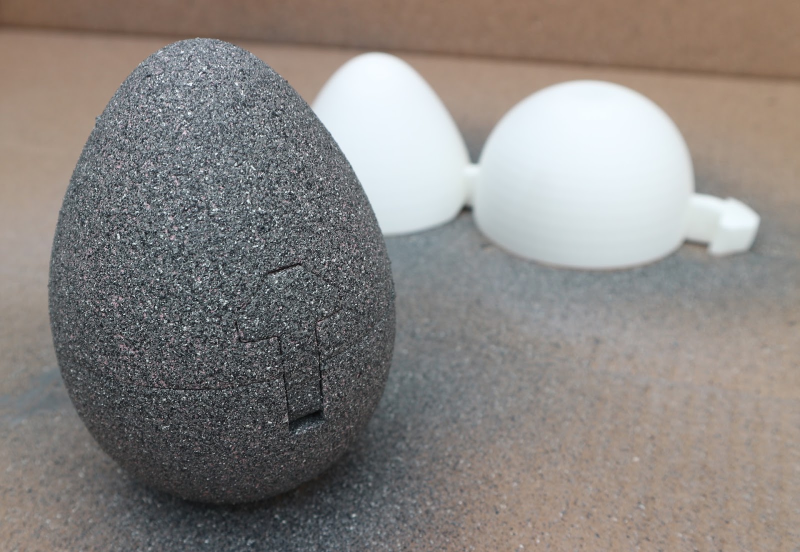
| One of the very first test prints of the ColorFabb LW-PLA - to work out the 'puff-point' |
TL;DR
Overview Summary -
LW-PLA is a really
unique material for 3D printing. It's somewhat challenging to
initially set-up, but when calibrated to your 3D printer, it can
produce great results and most importantly light weight 3D printed
parts.
You can print in both
it's natural state, just like solid PLA, and with increased
temperature a foamed state, so the same part can contain solid and
foamed layers or features, it's like having a multi-material in a
single filament. Foaming and density can be controlled by temperature
and flow.
These parts can be
further processed and finished, painted or coated as required.
Don't use in a machine
with a bowden extruder system.
You will probably need a bed adhesive, It's not quite as sticky as normal PLA, I found Magigoo worked well, and slow down your first layer about 20% lower than normal PLA speed.
You will probably need a bed adhesive, It's not quite as sticky as normal PLA, I found Magigoo worked well, and slow down your first layer about 20% lower than normal PLA speed.
Be careful with
extruder retraction – too much will make the filament expand beyond
the thermal break and block extrusion flow.
In it's non foamed
state, it's very similar to PLA, maybe a little more impact
resistant. In it's foamed state it can be sanded, painted and sealed,
very easy to post-process.
The foamed printed parts look and feel fantastic !
The foamed printed parts look and feel fantastic !
Quick Jump Index -
I have wanted a filament like this for many years, I have been doing a lot of material properties testing, experimentation and printing of parts. For that reason my blog post is going to be at least two posts, maybe more.
- Part 1 - (This post) - Experimentation, foaming calibration and initial strength / weight testing.
- Part 2 - (Next post) - Printing more parts, further strength testing and post processing / painting etc.
- Future More... - Mixing? / Colour? / Crazy settings and big nozzles...
LW-PLA Test Material -
Much of the initial testing was completed on a Prusa i3 MK3, the beta material supplied by ColorFabb was a reel of 1.75mm ~750g 'Natural colour' it's also available in Black. Tolerance and roundness of the filament was good.

Note:- If you print at
50% flow, it's like having a 1.5kg spool of printed foamed objects
'by volume'.
Start
settings and advice from ColorFabb -

ColorFabb included some guidelines and testing results with the Beta spool, showing how to calibrate a single wall cube line width so it is as per your slicer settings. This step is important if you wish to print parts that fit together and generally make accurate, repeatable foamed objects.

A primary focus in on
the weight reduction of parts because of the foaming, but I was also
very interested in the ability to make both hard and foamed features
with just a single material.

Simple
check to see what the foaming looked like – compared to normal
ColorFabb PLA/PHA

My first
test was to see the foaming in action – above is a cube printed
with a low level of infill, you can see the outer walls, they were 3
x 0.44mm perimeters and the infill is a single wall and rectilinear
infill causing the ridges every other layer.
After
printing it was cut in half and the cut edge sanded so you can see
the expansion above.
The Gcode
started at 200 Degrees C and for each layer increase in temperature
to 265 Degrees C.
Because
this was printed with normal PLA settings and 100% flow rate, the
material had no where to go, so both the outer perimeters and infill
became many times wider as the temperature increased, eventually
resulting in a temporary nozzle jam that corrected itself before
being stopped at 265 Degrees C. This simple print told me a lot about what was going on with the material expansion due to just a temperature increase.
Checking
the 'Puff-point' -

A simple
change of temperature every 5mm layer height, shows the change from
PLA to foamed PLA.

You can
even change the temperature by just 3 Degrees C and trigger the
foaming expansion point, showing this material has a good degree of
control and repeat-ability.
At this
point I have worked out various stable speed settings, so now to try
and tune the extruder retraction and temperature I am happy to print
the foamed material with - (spoiler alert – there is no magic
extruder retraction distance that solves ooze).
After some
testing with 'normal' PLA settings and just increasing temperature,
you need to start matching an extrusion speed (stable as possible)
with flow rate and also temperature.
As ColorFabb stated in the guidelines, you need to calibrate both flow rate and temperature to get a known and predictable rate of foaming expansion (rates of material deposition volume is also a critical factor). So that's what I set out to calibrate next.

The above
is a test object, with hex infill and 100% flow rate.
Below is
the same object, but a 50% flow, slightly lower temperature and
greater extruder retraction

As with
all material testing, you end up printing out a lot of test objects
with various settings to test the limits of the material and the
machine.

I spent some time trying to get a perfect extruder retraction setting, but it didn't take too long to come to the conclusion that it's almost always going to ooze if you are doing travel moves and not just 'vase mode' printing. Bu tit was very interesting to get a feel for the material, and experiment with line width settings, flow rates and temperatures.
It's also very tempting to change multiple things because you think you understand what's going on - it's often much better to change just one thing, then you will start to understand what's going on.

The final
'puff-point' test for me was to settle on a temperature I wanted to
use for more adventurous printing, I decided that 225 Degrees C gave
me a good level of foaming, and also minimal ooze. Again with 100%
flow rate, but in 5 Degrees C steps (Image below).

This
'puff-point' will depend on your print speed settings, so you may
well find that you see similar results as above, but at a different
temperature range. I was running at around 40mm/sec for most print
settings, and I found that to me quite optimal for using this material as it helps keep the puff-point temperature low (225) and that also keeps ooze to a minimum.
You can go crazy with high speed, high temperatures (250+) and you may get a 3x expansion or more, but I didn't find that to be useful when printing more complex objects with infill and islands - read on below to see more on that aspect.
With the above tests and more shown below I worked out that too much extruder retraction can cause nozzle jams and also does not stop the material from oozing - more about oozing later, as it's really not as big of a problem as it first sounds with this particular material.
After
the 'test cube stage' - (Nozzle Jam #1) -
At some
point you need to print more than test cubes, and for me the real
test was going to be complex objects that had a lot of islands, long
travel moves and a lot of start-stop retractions.

A good
test object is a quad-copter (drone) body (design by DV0001) – it needs to be light,
strong and has a lot of individual islands, large print area and
plenty of extruder retractions. To test my theory of extruder
retraction distance and high temperature, the above image shows an
early nozzle jam failure.
This model proved to be a perfect (difficult) test for the foaming material, if I had started printing with an easier model I would not have learned so much about the 'viable window of usage' and I bet I would have ended up having a lot more frustrating failures later on without understanding why I was seeing jamming etc.
This was also the first indication that a high flow rate flow rate, combined with higher temperature (giving a high expansion rate) and low layer height could be making nozzle jams more likely (when you also have long extruder retractions) - so I set out to discover what were bad combinations and what were better.
Nozzle Jam #2 – (Learning all the time...)

After a
tweak to the settings (see above in image), lower temperature(230
degrees C), increased layer height (0.25mm) and lower extruder
retraction (3.0mm) and a lower flow rate (50%) - The print made it
much longer into the print process, but still caused a nozzle jam before the
print was completed.
Print
success (No nozzle jams) –
Also don't be alarmed by the strings &
loops - I will explain why that's not a problem.

Critical
print success settings for me were –
- Low extruder retraction (under 2.8mm) - I now use 2.6mm extruder retraction on all foaming prints.
- 225 Degrees C with a matched 45% flow rate
- ~44mm/sec Print speed on as many settings as possible (32mm/sec for small perimeters)
- Higher layer heights (0.25mm to 0.35mm) worked better for the foaming process without causing nozzle jamming.
After I
decided on these settings, along with a print speed of around
44mm/sec and going no lower than 32mm/sec (apart from layer 1 –
that's also printed slightly cooler), I had no further problems at
all with nozzle jamming or print failures. Every other print from now on was a first time success.
Foamed
Benchy - Success!

MasterSpool
Success ! (Again, don't worry about the ooze-hairs on
the print – they rub off)


Both the
drone body and a two part MasterSpool print are significant sized
object, with a lot of features, islands and travel moves.

You can
see some bumps and spots, but they just brush off. A little nozzle
ooze is the one aspect of this material that is going to be almost
impossible to eliminate, but in reality it does not seem to cause any
problems for the printed object or the final finish after a little
post processing.

A
little bit of clean up -
The
internal stringing 'hairs' and excess material looks to be a problem,
but it's surprisingly easy to remove with just your fingernail,
scraper or a blade. Removal does not leave missing areas of print or
significant blemishes on the printed part.

The drone model and MasterSpool prints had quite a few hairs due to travel moves and oozing. But they clear off the model really quickly, most with just a brush of your finger or finger nail.
 |
| Straight off the printer, you are going to see some hairs and stringing, these are easily removed. |
A light sanding will remove most surface imperfections and you won;t even be able to tell it's been sanded because it all feels the same as a very slightly textured surface. It's hard to describe, but I going to say that most people will really like the feel of the finish using this material.

At this point you may be thinking that you don't want to print at 'big 0.35mm layers', but the printed objects do not in any way look like models printed at 0.35mm layer heights...
You really need to see it in person to appreciate how nice a 0.35mm layer height can look on a model -

Weight
compare -

Above
shows the drone (quad-copter) body printed in both ColorFabb Natural
PLA/PHA and the LW-PLA foamed at 45% flow.


PLA/PHA
(Above left) @ 56.7g LW-PLA 45% flow (Above right) 26.3g

Both the
Benchy prints above were printed using LW-PLA – Left it's
non-foamed @205 Degrees C and Right it's foamed @225 Degrees C with a
45% material flow. Now a Benchy can actually float!

Significant
weight reduction for the MasterSpool – and it's completely
functional in it's lighter and foamed form.


1cm3
printed at '100%' but foamed @ 45% flow is around 0.6g
Bend,
twist and strength testing (Materials and laminates)-
For
some bend testing I printed a number of combinations of PLA/PHA
and various laminates of LW-PLA.


Simple
bend test setup shown below -


Bend Test results -

Clearly a
fully foamed print will have more bend and flexibility than a
normally solid print.
Compared
to the weight, the strength of a 45% flow foamed object is really
impressive.
Test D
laminate shows a lighter weight object with less bend than a solid
(Test B) object.

More strength and layer bond testing -
To test
layer bonding, some single wall 'vase' prints were used -

Single
perimeter 0.35mm layers printed with a 0.4mm nozzle

PLA/PHA
test snapped cleanly across a layer.
LW-PLA
(not foamed) also snapped across a layer, but required more force to
make it snap.
LW-PLA
(foamed) did not snap, but folded – it was not possible to break it
by hand across a layer line, instead it required tools to rip it
apart. The foamed print tends to tear in whatever direction stress is
being applied. Layer bonding strength is very good indeed.
I don't want to make it sound like it's the strongest thing ever, a foamed print will have some level of strength, and will be much more impact resistant You can throw it on the floor - a PLA part would break, and the foamed part will just dent and bounce off the floor) It also will have better layer bonding, but it's not a highly 'strong' material in it's foamed state, it's just really impressive indeed for it's weight. That said it's not easy to snap or break by hand either.
To get some idea of comparative strength, just try printing an object in PLA with flow set to 45% - it may just about print, but it will be incredibly weak and will most likely buckle, de-laminate and fall apart.
Doing the same with the LW-PLA at a foamed 45% flow rate produces a remarkably well layer bonded part with a surprising strength to weight ratio, it can be post processed and it looks great too.
Summary so far -
Okay, so I have done a lot more testing of flexibility, post processing, priming, sanding, destruction testing, printing lots of different models - so far used almost two complete 750g reels of the filament (remember that's like printing 2.5k to 3kg of parts).
Below images are just a little preview of what ill include in the next blog post for foaming PLA -


My guidelines for successful use
of ColorFabb expanding PLA-
Don't use this material
on a bowden tube extruder system! - It's just does not work well.
A direct drive extruder
like the Prusa i3 MK2/3 or the Taz5/6 etc. is ideal.
If you are using a
glass or PEI print surface, I would strongly recommend using a
surface treatment – I tested glue stick, various sprays and
lacquers - then found that standard Magigoo for PLA worked the best
for me.
DO NOT adjust your flow rate by modifying the filament diameter or extrusion ratio in your slicing program, you should be using the following Gcode command in your starting script -
Examples - (Just use one of these at the end of your starting Gcode script) -
M221 S45 ; sets a 45 percent flow rate in the firmware for the ColorFabb Expand PLA
M221 S55 ; sets a 55 percent flow rate in the firmware for the ColorFabb Expand PLA
M221 S95 ; sets a 95 percent flow rate in the firmware for the ColorFabb Expand PLA
If you use the M221 command, you can then do nice things like set areas of your model to be printed solid (not foamed with 100% flow) and other parts to be foamed at 45% - You will not be able to do that if you mess about with the filament diameter of extrusion ratio.
All the testing /
tuning and experimentation below were done with a E3D V6 hot-end and
0.4mm nozzle. (I will be testing it out with other extrusion / hot-end systems too).
I intend to do some
further testing on the TAZ6 Moarstruder (Volcano 1.2mm Nozzle) if I
can get some of this filament in 2.85mm. I think the large nozzle and
a ~>2mm layer height may be possible and very interesting to see !
Make printing speeds
for different moves as similar as possible (where appropriate) –
basically try to avoid sudden changes in print speed / flow (other
than extruder retraction).
Do not chase a magical
value for extruder retraction – there is not a setting that will
eliminate ooze using this material – but you can minimise problems,
more importantly you need to tune the extruder reversal to avoid
chances of hot-end & nozzle jamming...
I can't stress how
important this next comment is – you WILL have an nozzle jam during
any significant testing and experimentation of this material. It's
not all that hard to clear a foamed blockage on an E3D V6, but it may
be more difficult on other machines / nozzles out there. You have
been warned!
Trigger point for
expansion 'puff-point' is dependent on print speed, temperature and
material flow percentage. - The instantaneous energy that's being
transferred into the material as it passes through the nozzle.
Extrusion volume, 'speed' and dwell in the nozzle plays a really big
part in getting a controlled expansion and repeatable material flow
for printing different types of objects.
In the past I have
experimented with printing PLA very fast indeed, it's not unusual to
bump up the extrusion temperature to 260+ Degrees C just to be able
to get enough thermal energy into the material at very rapid flow
rates.
When testing out the
Volcano and a Bondtech extruder on the Hangprinter with a 1.65mm
Nozzle the 1.75mm PLA feed needed to be well over 270 Degrees C –
just to get it melting and printing, and even that showed a slightly
matt finish, where the PLA being used would normally have been shiny.
You could slow things down but who wants to print big things slow :)
If however you let that
PLA material sit in the hot-end at that temperature during non extrusion events for too long it will quickly turn to the consistency
of honey and start to degrade and eventually burn.
The Expanding PLA can
handle very high temperatures quite well, but you also do have to
consider the energy, flow rate (deposition of material rate) and
thermal expansion rate of the filament carefully, so that means
tuning your slicing program so you get optimal conditions.
For a stock Prusa i3
MK2/3 I did not need to change any firmware settings, but did tune
Slic3r settings for more consistent results, especially with regards
to changes in print speed for different model features.
I found it best to
determine the ideal 'puff-point' with as consistent speed settings as
possible. This means smoothing out the changes in print acceleration,
for example inner and outer perimeter should be similar, infill and
even small islands need to be closer to all other printing speeds,
rather than very fast or very slow as you may have them when printing
PLA.
You can use fan cooling
– but only around half of 'normal' PLA settings. If you use more
cooling it will change the puff-point and limit expansion of the
material. You can even set cooling and extrusion temperatures to be
just a few degrees or percentage different per layer and see the
foaming form or not.
I used no fan for the
first layer and also a slightly lower extrusion temperature (222) to
compensate for a slower first layer speed.
Interestingly if you
print at around 195 to 205 Degrees C, this material will behave just
like 'normal' PLA. There is no real reason to do this unless you want
a more solid/hard feature in your expanded model or a multi-density
laminate like I tested above.
Trigger
points with hot-end jamming for me were -
Too much extruder
reversal – >2.8mm and it would jam every time at some point in a
'real life model' print where travel moves and island printing were
frequent.
I experimented to over
3.5mm extruder reversal – trying to eliminate ooze on travel moves,
but it just caused more problems (it's better to lower the
temperature to help combat oozing – see below).
If you pull the
semi-expanded filament back too far into the thermal break or
cool-zone it will jam.
Tune this to failure
mode and then back off – I have had 100% reliable printing of many
different types of objects after I lowered extruder reversal length
to 2.6mm for the V6 nozzle.
Every print would
always fail at over 3.0mm extruder reversal.
Generally the higher
heat you go, the more you will need to reduce the flow rate – if
you don't you will get very wide extrusion traces and that will be
much more likely to block the nozzle at some point during your print.
You will end up with a
combination of temperature, print speed and flow, that gives you a
'normal' extrusion width for your nozzle size, and then you can print
foamed objects with a similar accuracy and (often better) print quality than you get with
'normal' PLA.
Observations
for finish and post processing -
Don't worry about the
ooze / stringing / whiskers – they rub off easily and for whatever
reason you don't actually see any real defects in the finished model
– like missing sections of outlines or indents or bumps. You should
be 'loosing some volume' from your printed object, but due to the
foaming and general ability to blend layers together you don't see
these strings or bumps translate into lasting defects on the printed
model with just a little post processing clean-up.
Should
you try this material? -
Do you need light
weight printed objects?
As long as you are
prepared to tweak and tinker with the settings to tune temperature,
speed and flow with your specific 3D Printer, it is a really
interesting material that can give unique optical, mechanical and
weight related properties to 3D printed objects.
You can print 2 x as
many things with a 750g coil of filament...
You can actually print
parts out faster – even with slower print speeds... (Because you
can break the 'normal' slicing rules using the the same sized nozzle
- you can use a higher layer height and line width and even less
perimeters and infill for an object and it will still have well
bonded layers and a 'solid' finished form.
For me, once I had my
settings tuned in – I found I could print almost anything I would
print with regular PLA in the LW-PLA (Light weight expand PLA).
If you make lot of cosplay parts, props, models, buildings, prototypes and almost anything you would want to show off to a client (either with just a light sanding or full paint finish) I would say you have to at least try this material.
I have really enjoyed using it, and I find more uses for it every day - I can only hope one day ColorFabb decides to release #MasterSpool compatible refill coils of their filament, but if you can live with the fact it comes on a single use polycarbonate plastic spool... then I can strongly recommend trying out the material for 3D Printing.
Final
thoughts –
And a message to 3DP material manufacturers -
I'm excited about this,
not just the foaming filament, but the fact we are still seeing
research, development and advancements in filament's and materials
designed exclusively for the 3D printing process.
The other aspect is
that we need 3D printing filament (and resin) manufacturers to
actually release these materials to users. I say this because I have
tested many pre-release materials that were somewhat challenging to
use, and unfortunately this can mean that a manufacturer decided not
to release the product into the market.
We need challenging
materials, we need to work with or find ways around the limitations
and allow more people to experiment with exciting developments like
this foaming PLA.
I'm please that
ColorFabb have not only developed this material, but they have
decided to release it. It's not a totally 'simple' material to use,
and it will challenge some machines and users. But my message to all
materials developers and filament manufacturers is to let more of
your 'test materials' out for use. Even if that's with a lot of
warnings, 'alpha or beta status' or as E3D have done in recent years,
marked challenging materials with a 'here be dragons' labels.
Thanks for making this
a reality ColorFabb – I'm looking forward to seeing many more
materials like this. For me this is one of the materials I have been
waiting for since I started 3D printing.
That's all for now, I hope you enjoyed the (rather long) Part 1 Blog post about this material.
Edit* - Looks like I just got this blog post finished in time - ColorFabb have just announced on Twitter the release date and details for this material - find out more here - *Edit
See you next time, and if you have a new and interesting 3D printing material you want me to take a look at, do get in contact.
Rich.
Please join me on Twitter @RichRap3D if you want to discuss more about 3D printing.
My Youtube channel is here, all 3D Printing and Hi-Def video content.