Tuesday, 11 January 2011

Homemade Delrin Nuts for Z Axis - first go at using my Lathe

So the Plan with the Z stage is now to use M8 Rod and make some Delrin Nuts for it to move up and down.
I will change over to M10 Trapezoidal leadscrews if this arrangement actually works.

Delrin Bar stock and M8 rods.

Not bad for a first stab at it? - Delrin seems easy to machine on the Lathe, much easier than Aluminium.
I don't need it to look pretty as it's going inside the Z framework.

Drill out a 6mm hole so I can hand-tap the M8 Thread.

Needs to be parted and cleaned up.

Hand Tapped and ready for ramming into the 30mm x 60mm Framework.

They line up with 10mm Holes drilled through the frame so the M8 rod can run up and down.
The Rectangular nature of the centre hole digs into the Delrin and stops it turning around.

M8 Rods cut to size and an 8mm Clamp and washer is used to translate the load onto the bearing.

This mount allows the bearing to rotate and fixes movement.

Seems to work well.


I has a small problem with my Flexible motor couplings. They were 6.35mm and the shafts of a NEMA17 motor are 5mm, so I used a section of 6mm Nylon tube and heated it in a kettle for 2 mins then forced it onto the motor shafts, giving a very snug fit on the coupling.

NEMA 17 Motor (one at each end)
Then Flexible Coupling.
M8 Rod
and Delrin nut inside the Frame Mount for the X Axis.

So the updated RepStrap V2.0 Machine now looks like this.

I need to make the Ballscrew mounts tomorrow, so more updates shortly. 

Rich.


Sunday, 9 January 2011

V2.0 X+Z

Machine stripped back to just the frame and now the Y axis (bed) is moving so no more slow Gantry. This means that the frame is fixed in the middle for the X and Z stages to move on and Y will move back and forth like Mendel.  

Frame is made from 30x30 and 30x60 Aluminium MCS (Machine Construction system)
Some parts like the bed and Extruder mounts are made from 20x20mm to reduce size and weight.

Most of the mounting brackets will be re-made from Aluminium Angle and a small number of parts made from Wood or Polycarbonate, like the motor mounts and Ballscrew attachments.
X Stage mounts (x 2)

Drilled - ready for assembly.

The two X stage mounts hold the two 12mm Rails using off-the-shelf rail clamps.
X stage that is mounted to a 30mm x 60mm Rail to attach to the moving Z frame.

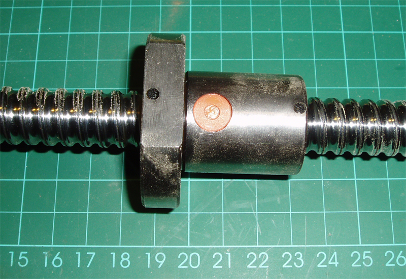
The Linear bearing blocks ( x 4, only 2 shows in photo) and the 16mm Ballscrew allow 32cm of X movement.


Z NEMA 17 Motor Brackets (Left and Right mirrored) from 50mm Alu Angle

Drilled - ready to mount the two NEMA 17 motors that will drive the Z axis.
Flexible motor couplers connect to the Z drives (M8 rod for now) maybe change to Trapezoidal lead-screws later (if it all actually works)...

Looking like a machine again. You should be able to see the 16mm Vertical rails that guide the X stage up and down.

Wiring should be integral into the frame (but I may decide not to do that).
It should be easily enclosed in Polycarbonate or Acrylic if desired.

The next job is getting the whole Z axis to move on home-made Delrin bushes. I plan to fix them inside the 60 x 30mm X Axis frame so it can move up and down. This will require my now working OLD Lathe and it will be the first time I actually use it for anything.


Rich.

Friday, 7 January 2011

Goals for RepStrap V2.0 Machine

My Design Aims for the RichRap RepStrap Version 2.0 Machine are - 
  • Faster print speed - (This is my main driving factor after having a slow Repstrap for 6 months).
  • Change to Ballscrews on X and Y Axis (not sure about Z at the moment).
  • Revised Electronics (Mega based - interim version for 2011, until I get my other set finished).
  • Integral Electronics Tray and wiring with reliable connectors.
  • Change from a fixed to Moving Y bed and print platform.
  • Remove the Gantry head arrangement for the Z axis - Need to think of a simple way to do this...
  • Simplify the Z axis by using dual Nema 17 motors (I may regret that decision...).
  • Increase build-area to 300mm x 450mm x 300mm (Y being easily changed from 100mm upwards).
  • Have easy-fit/remove build platform at different sizes and thickness.
  • Vertical mount Extruders.
  • Dual Extruder ends with remote mounts for Bowden mounted extruders
  • Switch to Herringbone Extruder Gears.
  • Filament coil store and supply feed for 2 reels built into the machine.
  • Heated bed.
  • Resistor block Hot-ends.
  • Multiple Thermistors / readings.
  • Use as many off-the-shelf components as possible.
  • Use the off-the-shelf parts to maintain quality and accuracy in the design.
  • Do the minimum amount of machining as possible. - But I may do some just for fun as I have a shabby Lathe and Band saw now.
  • Where I need to do machining then it needs to be non-critical or easily adjusted to retain quality.

I Intend to be inventive to keep costs down.

* I don't intend to use Belts in this model, but I have a long-term plan for a miniature design using belts instead of Ballscrews maybe directly after this one.

So why don't I just make a Mendel?
 - Well I like the thought of a machine I can build and design myself and I have learnt alot from the first attempt last summer.
And finally it should cost the same to update my RepStrap as it would to make a Mendel, so here we go!


First Z Motor Mount plate (50mm Alu Angle)

First parts of the new X stage, supported with 16mm Linear Bearings and a 30mm x 60mm Aluminum frame that will incorporate the Z vertical movement by using Delrin and leadscrews.


The above plan may sounds like this will be far away from the reprap project goals as it's still using Aluminum and machined components, but I intend that this machine will make it easier for me to develop real self replicating machines in the future. Also Aluminium is 100% recyclable so on that front it's not anti-reprap.

Rich.

Thursday, 6 January 2011

The Plan! RepStrap V2.0

I have no machine! it's stripped for a complete makeover...

The RepStrap makeover uses more MCS Aluminium framework.

And Ballscrews for the X and Y Axis.
Z Axis will be Trapezoidal lead-screw or just M8 rod to start with.

I also invested in a Fury3 Chop-Saw for Christmas, this can cut Steel, Aluminium and Wood with one blade - Nice!

Some off-the-shelf Internal R/A fittings and also external brackets will be used this time instead of R/A cut Aluminium.


It's easy to cut, drill and fix together with T-nuts and bolts.

And the last things I printed with Repstrap V1 before taking it apart included a load of Extruder parts, including these nice Herringbone Gears by Rhys Jones -Here > Thingiverse - Rhys Jones Herringbone

Quite a few people have done work on Herringbone gears, Forrest Higgs has a nice post here about them Here > -Forrest Higgs (Herringbone Rack and Pinion) -

Forrest's RepRap Blog is here -http://technocraticanarchist.blogspot.com/ 

These parts will hopefully get me printing again if the V2 RepStrap does not go to plan...

This is the point I should have made a 3D model of my new machine, but I have a whole load of Ideas that may or may not work and I always find it better to evolve as I go.

I'm going to start cutting Aluminium later, hopefully I will have something to post in the next few days, and I'll try to get up a list of what I'm planning to achieve with this new design.

Onwards - >

Rich.


Wednesday, 5 January 2011

New Tools for Christmas and a start on my RepStrap Overhaul.

Happy New Year Everyone.

I had some new Tools for Christmas and have finished restoring my old Lathe to working order so I'm going to start my planned upgrade of my RepStrap - This time around I'm going to make more notes (Eventually for the Reprap Wiki, I hope) make some design drawings and take lots of Photo's.

BandSaw for Christmas. – Now unpacked and Running.


More Aluminum MCS sections for a new design.

30 x 30mm Alu MCS Frame

30 x 30 and 30 x 60 Brackets.

30 x 60mm Alu MCS Frame

Received a set of Ballscrews and rails for a complete overhaul of my Repstrap, more pictures to follow.

I'm going to strip my current Repstrap later and start the rebuild tomorrow.

Rich.

Friday, 17 December 2010

Restore of OLD Lathe for ongoing RepRapping.

So I got hold of a very old looking Metal Lathe, it had no motor or any cutting tools, but it was so cheap it was almost given away to me and it looked like fun to try and get it working again.

A few extra parts/heads (for woodworking I think?)

But it did need a Motor and some TLC before this was going to work.

Taken apart and I mounted it on some old Oak worktop along with a 1/3HP AC motor and a new belt drive. Both the motor and belt was salvaged from an old Pillar drill.

I added a Polycarbonate shield, On/Off switch along with a belt adjuster made from a spring and an M8 Bolt.

Got hold of a cheap set of 1/2" Metalworking tools and it all seems to work. Nice and stable, but I'm not sure how long the old brass bushings will last?

This is really going to help with re-construction of my RepStrap and some new hot-ends I have been working on.

If anyone knows what model or how old this would be let me know, I'm interested and would like to know more about it's origins.

Soon to be used for something cool...

Rich.


Saturday, 27 November 2010

Geared Extruder Hot-End Block finished

My new Aluminium block and resistor heater is finished and is printing very well, here is how I made it -

Drilled holes for the Brass nozzle, two resistors, one thermistor and a locking screw to keep everything tight.
Do this with a long length of Aluminium as it's much easier to clamp and work with, you can cut it down later.

I used two 3.3Ohm Resistors - Wire Wound 3W these will be wired in series- vishay-resistor-ww-3w-5-3r3

Cover them with Aluminium tape (or foil) and insert them into the Aluminium block with a little Heatsink compound if you need it - They should be a tight fit.

Then you can use some Fire Cement to hold them in and seal the ends - Bake at 200 Dec C for 15 mins.

Baked

Assembled.

Thermistor fitted into small hole and the resistors connected in series (crimped).

After a few z calibration problems with my last extruder I wanted an easy way to adjust this one, and also a quick to change it over, so this R/A Aluminium mounting plate will give me all that and some extra heat-sinking of the PTFE guide and Extruder.

Slide slots cut, so I can now easily adjust the Z height - really good for testing bed materials that may have different thickness etc.

Now to fit it all to the WADE Geared Extruder - 
All Assembled and wired up.

Done - And the first test cube printed.

Fitted to my Repstrap V1 and after a bit of calibration for the new Extruder feed-rate it's printing extremely well, and giving 100% better prints, and I also now don't need to print a shield as the tiny surface blobs I experienced with the Pinch extruder have all gone.

The Extruded filament is very smooth and consistent, and is producing great results, I'm delighted !

It's printed for about 10 hours now with this new extruder build and still working perfectly, so I can call this a success and move onto upgrading my Repstrap so I can get the print speed up...

RichRap.