Showing posts with label sketchup. Show all posts

Friday, 1 June 2012

#30DoC Badge & simple guide to manifold 3D design

I'm starting the 30 days of creativity month with a two colour #30DoC printed 3D badge designed in Sketchup and printed on a RepRap 3D printer.


If you are new to 3D printing, take a look at my Blog and on the RepRap Wiki pages.
If you want to explore the sorts of things you can print with a 3D printer, take a look at Thingiverse

Here is how it was designed and printed -
Open up Sketchup and import a picture you wish to trace or use for inspiration (File-import - Jpg)

Go to 'View' menu bar face-style and select X-ray, this will allow you to see the picture below any 3D objects you place over the image, you can trace around things or align parts to the image.

You can now draw circles and add text, push-pull the various sections to make the model.

With this badge it's going to be printed face down so the text and the X are pushed into the face, allowing for the second colour layer to be seen from the front.

We need to draw and add a simple safety pin clip holder on the back - we will insert the clip while printing!

Export 3D model, slice it and print it out, starting with yellow plastic.

After about 7 layers or while it's still doing the last of the text outlines, switch over to Black plastic.

Let it print the rest of the back and get ready to pause printing when it has done some of the clip.

After is has printed half of the clip when it has a channel, pause the printer while it's doing an infill and insert a  safety pin into the channel and tape it in place. Resume printing

The pin will be trapped and after it's cooled down you can wear your badge with pride, and it's bound to bring creative inspiration for the rest of the month.

The 3D file is up on Thingiverse here, along with the Sketchup model, go print one out!


A very simple guide to making models that are manifold (valid) for 3D printing -  
While I was making the badge in Sketchup I had some of the usual errors you get when joining sections of modelled parts together (the text onto the badge face), so as a guide and tutorial here are a few notes about how to make a simple 'manifold' object for 3D printing.

Background - 
Objects for 3D printing are usually .STL files, the information in a STL file describes the 'mesh' of the model using points and faces, basically made up of lots of triangles joined together describe the surface and contours of the model.
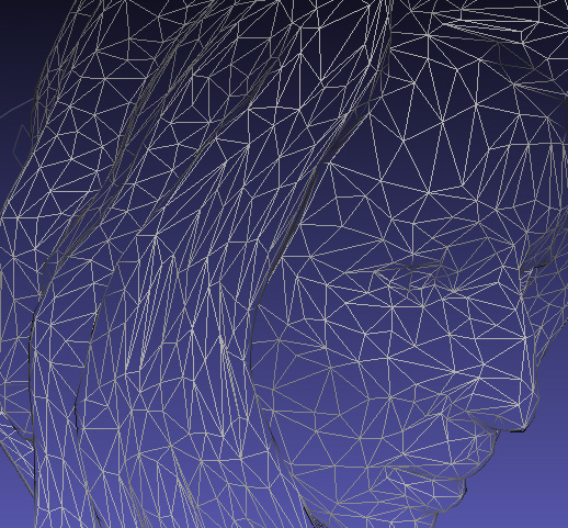
Typical model 'mesh'

Unlike a photo with a set maximum resolution, you can print a 3D model at any size you like, the triangles just get bigger, so you don't gain or loose detail and with most current fused filament 3D printers, if you enlarge a good model you will see more features being printed that were not possible with a smaller size due to the nature of the filament printing process.

This means that the model has a 'Quality' depending on number of triangles describing the surface, I will go further into model quality in another post shortly, but a basic example is shown below -
Top model uses many triangles and can be considered high resolution, middle is half the quality of the top and the bottom is a quarter of the quality / resolution.

Back to valid meshes - 
If the mesh is valid and said to be 'manifold' is will have a surface without any defects, these can be holes in the faces, triangles that intersect each other, faces that share the same plane and other odd things like triangles or objects inside other complete meshes that basically make the object invalid.

If a 3D mesh has a problem, it's usually called a 'non-manifold' model, these can be repaired using programs like Netfabb but when designing 3D objects to be printed it's best to try and find and fix problems in the source rather than attempt to repair them later.

Many 3D modelling programs will allow you to join (union) objects together, (the basic free Sketchup does not let you do that automatically) programs like Autocad123D should make a valid mesh out of the two objects, and all you may need to do is remove the part of the object that was not part of the union. But it's always good to be aware of potential issues with 3D.

Example with two cubes - 
Step 1
We start with two cubes both are components to make it easier to move them together and so they won;t interact unless you want them too.

Step 2
The two cubes have been pushed together, this has made a non-manifold mesh, the cube faces are intersecting each other, so this would not print as you woudl expect from the above image.

Step 3
If you delete the front face you can see the problem.

Step 4
To fix the problem we are going to draw lines around the cube on the surface of where they meet, the red section inside the box is now the problem, but as we have just isolated it, by drawing the lines around the meeting point we can now remove it.

Step 5
After deleting the red cube, you still have a face inside from the dark grey cube, you need to delete that next.

Step 6
 Now you have a hollow mesh of the two cubes, this is almost a valid object, you just need to replace the front face by drawing a line down one side and it's done.

All finished


You can get the sketchup file on the thingiverse page Here


Thanks for looking, and see you for more #30DoC tomorrow.

Rich.

Friday, 1 July 2011

Layer selective colour 3D printing

After printing coloured and multicoloured things, I wanted to experiment using my Filament joiner to make prints that had different coloured finishing layers (at different heights) on an object.
A business card seemed a suitable object to start with as I could place things and text onto it and vary the height of each object.
This is what I ended up with, below is how it was done - 

First I actually needed to learn Sketchup so I could design it. I had quick go as hacking other peoples parts a few days back but as I wanted the open hardware logo on the card I needed to work out how to do that first.

Download a picture
Import it into Sketchup and turn on Xray
then trace around the image to form a closed path you can extrude

Extrude that to whatever height you like
Then I added text using Sketchup font tool.

The model should turn out like this.

Design the rest of the card
Each text block finishes at a different height from 0.8mm to 3mm

Export and re-scale in Netfabb if required
this is 85 x 55mm

I did a quick test of fonts to see if they would actually print – 
This just showed me that you need it to be an outline without any infill or it will end up messy.
I could have made a better selection of font and size, but not bad for a first print.
I need to work on the font size so Skeinforge produces a tool path that does not try to fill little gaps in the letters.


Then after slicing in Skeinforge you can use the output Gcode and a program like Grep to isolate out the extruded movements for each layer.
Then you can join the sections of filament together the correct length and print !

At each point you decided should have a different colour the layers change and slowly build-up a multicoloured object.
The red text is only two layers high and a little smudged.

It looks good enough to eat!


A few other multicoloured things printed for fun yesterday.


close up, the changes are quite sharp, I initially imagined it would take many layers to change colour.

I had a go at also doing horizontal selective colouring on the base, but it's not easy to see in this picture.


The inside of both bases lines of different colour so with correct filament lengths you can select  both horizontal and vertical colouring.
If you were printing a cylinder for example, with the correct lengths of filament you could colour half of the object in the vertical plane as it was being built up (quite hard to do though).

Fitted together perfectly.

Many thanks to AgeingHippy for sending me some white PLA to try.
And thanks again to Greg Frost for suggesting using Grep for working out lengths of input filament.

I need to get ready for the RepRap weekend now, so thanks for reading (quite a long one this time).

Rich.