Showing posts with label setup. Show all posts

Friday, 7 April 2017

LulzBot TAZ 6 Testing Part 2 - Problems, Printing, Materials and Tuning to perfection.

For this second part of the TAZ6 setup I'm looking at some initial issues found with the setup and operation of the TAZ6. These were quickly resolved, but showing you the process may assist if you have similar problems on your 3D printer.

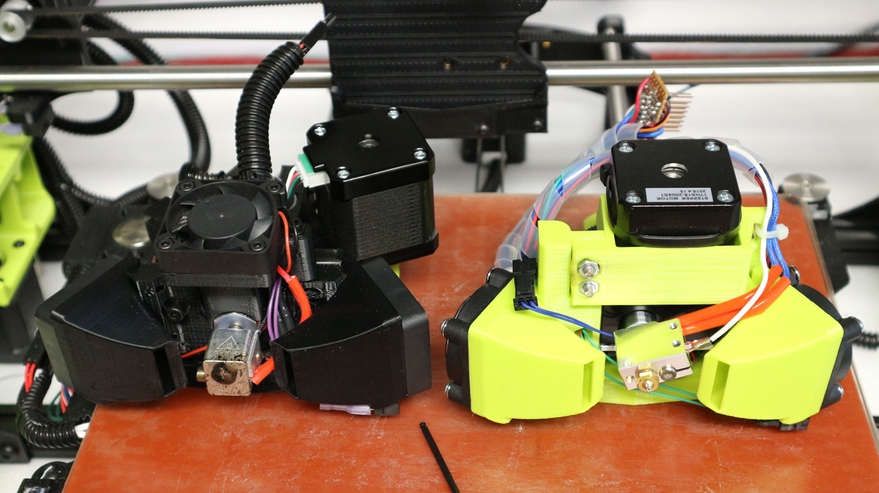
I was also sent a MOARstruder by the LulzBot team, I talk about it in the video along with a custom tool-head I have made for the TAZ 5/6 using the E3D Titan AERO extruder+hot-end.


Further details about the MOARstruder can be found here, on the LulzBot Website.

The MOARstruder has a 'Volcano' compatible 1.2mm nozzle and long heating block for 100g+/hour deposition rates.

I'll post a separate blog and video about the Titan AERO extruder mount for the TAZ6, I'll also post the files if you wish to try to out too. The Titan AERO saves around 178 grams in weight over the original Hexagon tool head, so you can fling it around faster too.

Further details about the E3D Titan AERO extruder and hot-end system can be found here, on the E3D Website.

The first blog post (Part 1) and video about the TAZ 6 can be found here


The Video below is also over on YouTube if you wish to watch in HD and also subscribe to my channel for more videos, help and advice.


If you want to skip parts, then here is a quick jump index -

00:10 - Intro & Catch up
00:50 - I have a MOARstruder !!!
01:15 - We can print MOAR
02:10 - 3Kg of Polymaker PLA
03:10 - Special Colorfabb nGen
05:00 - E3D Titan AERO on the TAZ6 (Volcano)
06:40 - Mesh Bed levelling setup advice
09:15 - Tweaks, changes & results
09:30 - Setup problems & solution

I will post an update on the print progress with both the MOARstruder and the Titan AERO on the TAZ6.

I'll also tidy up and share my firmware setting changes and print profiles I'm now using for TAZ6 printing. I initially started with PLA, then nGen and PETT (t-glase). I still have Nylon, flexible and composite profiles to generate and test.

On with the 3D printer setup and a few wiring problems...

I had one initial problem with the SD card reader built into the TAZ6. The SD card was not being recognized on the LCD display as being inserted.

First I thought that the SD card may just have been blank or faulty, but after checking it had some contents and was formatted correctly I investigated further.

This cable for the SD-Card connector had fallen off - I'm guessing during transport.

After opening up the side panel housing the power supply and the main electronics control board, I soon spotted that a cable was hanging in mid-air over the main RAMBo control board. When checking this was easily identified as the main serial connection to the SD card mounted on the user interface LCD display board.

Only 4 pins of this 8 way connector are being used, that's not a great deal of friction to lock this connector in place. If you look at the connector in the bottom right, you can see that spare unused pins have been fitted into the 8 way connector. Adding these unused but fitted pins adds more friction and helps to lock the connector onto the mating pins. Especially important on this cable as only two pins are connected. A much better solution is to for positive locking connectors to the RAMBo electronics board.

I checked the correct orientation and connected the cable back onto the RAMBo board. this resolved the SD card reading problem, and allowed me to get started on a test print that's included on the supplied SD card.

This was a simple problem and a simple fix, but for anyone without the confidence or desire to open up the TAZ6 it may have been only fixed by returning the machine to the supplier or manufacturer.

This cable and a few others used on the RAMBo are not 'positively locking', this means that they could fall out with a sudden jolt or unfortunate movement of cables. In this case it was probably during transportation as LulzBot would have checked (and indeed they supply a printed check-sheet of machine functions) that the SD card interface was working before leaving the factory.

This connector for the SD card also only has a few connections fitted, this means that it has quite low friction and is even more likely to fall out. Over the last 25 years as an electronics engineer I have seen a number of ways to combat this problem, you can simply add more crimps into the spare unused pin positions as a way to increase connection force (friction) as seen above. But the best way is to use locking connectors on the electronics board. The basic box header connections usually fitted to RAMBo (and other 3D printer electronics) are very low cost and used everywhere. You can get compatible shrouded box connections that incorporate both polarizing features - to ensure the connector is not connected in reverse or off-set and also a plastic locking clip that will keep the connector mated until you want it to be removed. They would be a drop-in replacement, so would not require any changes other than a different supplier on the electronics bill of materials. One other nasty way is to add a drop of hot-melt glue or silicone to physically 'lock' the connector cable to the board, but that's really not a good solution.

In my view, changes to this and some of the other connections ( housings and mating cables) on the RAMBo board would significantly reduce the chance of cables becoming accidentally dislodged in use or transit.

I would be interested in knowing if anyone has had a similar issue with this or any other electronics that do not use positive locking connectors (comment below if you have or have an opinion on this issue).

On the plus side the wiring inside the electronics box is tidy and many attempts have been made to improve the safety factor for anyone opening up this machine. Mains voltages are well routed with correct terminals crimped and fitted so minimal exposure to live parts are exposed.

Obviously make 100% sure the mains power input is removed and disconnected before you open up any 3D Printer or any other device for that matter.

The power supply is also CE marked as is the entire machine. Along with both European and American EMC testing standards.

As well as a CE mark and electrical safety, it's obvious that this machine has also gone through EMC and electrical standards for operation and interference. That's a really good thing and something that we still do not see on many other 3D printers sold as kits and fully assembled machines.

The round grey ferrite filters shown in the images below, are wrapped around various cables. This indicates that during machine testing of EMC and EMI areas were identified that needed some suppression of electrical noise.

The mains input filter (metal can in left side of image above) also helps to reduce conducted emissions back down into the mains of your house (and other people's houses).

Usually long cables like motor connections for example will act like ariel's attached to the electronics, these can radiate electrical noise and can also pick up radiated electrical noise from other equipment around you.


 Adding a ferrite clamp can often reduce these problems and allow EMC approval of a machine like a 3D printer.


Seeing these indications of a well designed, carefully assembled and correctly tested product makes me very happy. It's something many users don't even think about, but when you have a product with heating components, high currents and moving cables, I would strongly urge you to ask the questions - Has the machine you are considering been both safety tested and passed relevant electronic approval standards for your country?


Top tip for limiting the use of Mesh bed levelling -

If your 3D printer uses mesh bed levelling (it takes a number of probe point measurements across the bed and uses this to compensate for an incorrectly levelled surface) - Then do spend some time trying to get the bed manually as level as possible.

Why? - Basically because when the hot-end moves around the build area it has to constantly raise and lower the Z axis. The Z axis is the slowest linear movement on your 3D printer. Having a poorly setup bed is also more likely to cause print issues like blobs or strings if you are doing long travel moves, where the mesh levelling compensation is adjusting for +/- >0.5mm of uneven surface.


* Update* - The next two images show an example of how to level the X/Z axis. Below the next two images are also some pictures I used as an example in the video of how to help minimize Mesh bed level movement. The measurement distance on each side of the TAZ6 are slightly different (~3mm) so to make sure you level correctly for the TAZ6 3D printer please follow this link here from the team at LulzBot. - 
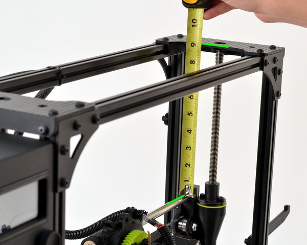

The LulzBot team measure the lengths from the X axis bars to the top, and that's a much better way for the TAZ6 3D Printer.
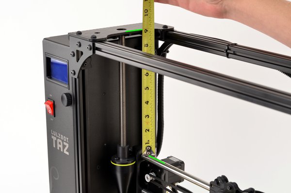


For many 3D printers using mesh bed leveling you can measure each side of the Z axis, and manually turn each lead-screw so they are the same (Again, do check how to do this correctly for the TAZ6, see above).


The most important thing is that the nozzle is at a level and flat point across the entire build surface, so if the left and right lead-screw are at different positions, then that's fine. 


Then check if that has actually made the nozzle distance the same on each side of the build surface.
If not, then adjust so wherever you manually move/place the nozzle (move X / Y carriages) it has a similar distance from the build surface (+/- <0.2mm if possible).

You will get better results if you do this, and you can then also start to tune the firmware to reach higher operating speeds and smoother print results. I'll go over my TAZ 6 Firmware changes in a future video.

Just to give you a sense of the change a few firmware and slicing settings can make to the end print result, take a look at the images below -

First layer of the shelf model - It's perfect.
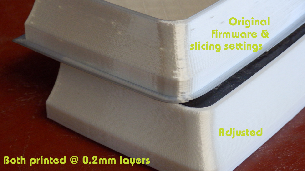

Top part in the image above was printed with the original TAZ6 firmware settings and default Cura profiles for TAZ 6 PLA.

The lower model was printed at the same layer height, same infill and same number of perimeters. The difference was a few firmware changes and revised profile settings. The bottom model also printed around 20% quicker than the original setup.

I use Polyalchemy Elixir PLA to test print quality, it will show up the smallest flaw in printing settings, so it's great to refine your profiles and acceleration settings.

The above model is the really nice secret shelf by Tosh You can get the file here

I'll show more examples of these changes with printed models in the next TAZ 6 video.


Before I made the firmware and profile changes, I did print out the samples Gcode models on the supplied SD Card. They show up some print issues, but they can all be resolved with setting changes.


Printed in Colorfabb nGen (light grey because it shows up defects well to the camera).


You can see some missing perimeter sections in the top of the funnel above.


We also have a few blobs and retraction strings, all of these problems can be resolved. And when they are the TAZ 6 becomes a stunning 3D Printer.

3DBenchy - Attribution: CreativeTools http://www.thingiverse.com/thing:763622

I'll continue to add more video's and blog posts about the TAZ 6 adventure as they get completed. Please leave comments and feedback below. And I'm really interested in also hearing from any existing LulzBot TAZ owners.

I hope this was useful, thank you for reading & watching, see you next time.

Rich.


Please join me on Twitter @RichRap3D   -  https://twitter.com/RichRap3D

Files and designs shared on YouMagine - https://www.youmagine.com/users/richrap

Files and designs shared on GitHub – https://github.com/RichRap

Files and designs shared on Repables - http://repables.com/u/richrap/

My Youtube channel is here, all 3D Printing and Hi-Def video content.


Monday, 13 March 2017

Using the LulzBot TAZ 6 3D Printer - Part 1 Setup


TAZ 6

LulzBot are without doubt (in my opinion) the most open-Source 3D Printing company in the world.

Here is the start of my journey with the TAZ 6 3D Printer.
I could spend an entire blog post just telling you how LulzBot have open-source in every single aspect of their business. Not just the 3D printers they design, develop, support and manufacture, but all the systems they use, computers running them and well just everything. If someone told me they only drank open-source coffee? I would not be surprised in the slightest.

To the point they will contact independent developers (anywhere in the world) and help them finish, refine and improve a little-known open-source software package, because they would like to use it in their business too.

Just have a poke around on the LulzBot development site if you want to be impressed by Openness - http://devel.lulzbot.com/

LulzBot (and the Parent company Aleph Objects inc.) support many independent projects and diverse developments, they don't always shout about it, they just get involved and encourage. If I lived in the USA I would be camping out at LulzBot HQ.

We need to see more of these manufacturers in an amazing community like 3D Printing. I hope LulzBot always manage to stay that way. Anyway, enough of that. You can see I have a lot of time for the LulzBot team, their products and everything they stand for.

My admiration of LulzBot is not going to stop me from a detailed (and sometimes critical) look at their 3D Printers, software and generally the user experience with all of it. They thrive on all feedback and it's one of the fundamental aspects of open-innovation, so here we go with a first look at the LulzBot TAZ 6 3D Printer.

I'm not going to attempt to 'sell you' on this 3D printer. It's been out for a while and has already won awards on 3D Hubs and has a good reputation in the 3D printing community. You can make your own mind up about the machine. See if it's right for you and at the price point and feature list you need.

I'm not even going to go into detailed specifications about print size or capacity, you can google that or just look on the LulzBot website. I'm going to focus on the experience and how reliable it is over a long period of use and abuse in the real-world and how it handles lots of different materials.


I hope to be able to show you what it can and can't do over this and more blog posts and video's. If you have any questions or want me to try something specific, just send me a message (twitter is best, but anything usually works - apart from carrier pigeon).

If you watch the first video below (it's long, but I make no apology for that) you will see that you get a really good first experience with unboxing, assembly and setup of the TAZ 6.

I hardly ever do 'unboxing' video's, but this machine just deserved a showcase.


Quick jump index -
01:28 - Materials
03:35 - Unboxing the TAZ 6
06:15 - MOARstruder ???
12:30 - Approvals, regulations, safety
17:00 - Taz 6 Assembly
28:50 - Power ON...
30:30 - Handheld Gaming (3D printed)
32:55 - In the next TAZ 6 Video

I have always been a huge fan of the LulzBot 3D printers, I printed out and built up one of the very early prototype TK-0 machines back in 2013 (an early version of the TAZ design) I made many modifications and eventually dedicated my variant as a portable machine to use at shows and events.

During discussions after the TCT Show in 2016, the team from LulzBot kindly offered to send me a TAZ 6. This is not only great, but as it's a machine that is not normally seen in the UK / Europe I really want to help support the growth and awareness of LulzBot products (and their open-source / Open-Innovation nature).


I did have some initial setup problems, I will go into detail in Part 2 of this blog post and video series.

A pesky dislodged connector caused me some initial setup problems, but it was quickly identified and resolved. Much more about the problems, issues and resolutions in the next video / blog post - along with lots of 3D Prints and feedback about both print quality and user experience.

LulzBot also sent me over some materials that are tricky to find over in the UK or Europe. These have been really great to try out and do work exceptionally well in this 3D printer.

 LulzBot standard ABS Filament.

 Chroma Strand Labs Inova-1800 Co-Polyester.

 The only Taulman3D material I had yet to try out - Taulman n-vent
 And Verbatim PLA.

LulzBot also included some sample filament in the TAZ 6 Box. This is what you would get if you just ordered the printer - Very nice filament from Proto-pasta and Colorfabb.


Initial assembly is very straightforward, a detailed manual guides you through all the steps and provides great advice along the way.


Every single part (including the full set of tools provided) feels high quality and 'engineered' to a fine level.


I talk a lot about the approvals and regulations for this 3D printer in the video (it's a very good thing). I'm not going to repeat myself here, but do watch the part about 3D printer approvals (12:30 onwards) as it's good to know why fully assembled, well designed and tested machines are worth the extra cost etc.


Noise level is acceptable during setup and also full operation. It's around the same overall noise level as a Prusa i3 MK2 (normal setting) the Prusa quiet setting is slightly lower. The TAZ6 has a lower frequency to it's noise level output (slightly bigger fans than many 3D printers) so feels less annoying and less distracting in the background. The TAZ 6 is a lower overall noise level than the BCN3D Sigma (2016 version).

I have no problem with the TAZ 6 running in the same small room when I'm 1.5M away from it.

 Bucket O' Octopi by yeoldebrian, published 

A test print Octopus (Above) was included, I had no problems replicating and exceeding this print quality with the Taz 6.


We did plenty of  'play printing' over Christmas, lots of the standard objects, test prints and plenty of decorations. When it was all dialled in I started to explore what the TAZ 6 could really achieve.


The Red Chroma Strand Labs filament was really nice to use, and strong. I designed and printed some hooks for hanging objects to rafters, they were clean prints (just look at those perfect layers) and very strong indeed. I'll see if I can work out a way to break these and compare the results with PLA or ABS for the next blog post.


It was not long before 17+ hour prints were being tested and then multi-day objects in ultra fine and full build area dimensions. (more on that next time).


As default it is set to print quite slowly. The default profiles for Cura have a low speed of travel rate, it can handle a lot faster. The firmware (Marlin) acceleration feels slower than my normal settings. There is nothing wrong with going a little slower and having a lower acceleration, in fact it can improve both print quality and further reduce noise level.

The issue is more with the fact this printer can print BIG, so really you are going to need a compromise of both speed and quality for some bigger prints if you want them to finish in a working day or before going to bed. That's no different to many 3D printers, so this issue is not aimed at the TAZ, just an observation with bigger build areas in general.

LulzBot have installed a 0.5mm nozzle as standard. This provides a a good mix of speed v quality in many types of printed model. The original RepRap 'standard nozzle size' was 0.5mm, but over the last five+ years it's now much more common to see a 0.4mm being fitted to almost all 3D printers.

You could replace the nozzle, but if anything I may decide to go even bigger, this machine is just crying out for a great big nozzle to produce some serious 3D prints fast and accurately. And on that point I had hoped to be testing out the now MOARstruder, but sadly it was not quite available when I asked about it.  (see below).

MOARstruder is now fully available for the TAZ5 and TAZ6 directly from LulzBot on the website, you can check it out here.

After a lot more printing and testing with the TAZ6 Hexagon hot-end, I'm probably going to make a new extruder for the TAZ6 using the E3D Volcano. The Volcano is very similar to the new MOARstruder, in fact the nozzles are interchangeable for the Volcano ones, so you can fit hardened, stainless, brass or copper types.

In the next LulzBot TAZ 6 blog post (and video) will go into a lot more detail about the print quality, settings and use of both Cura and other slicing engines on the TAZ 6.

The TAZ6 did a lot of printing towards the end of 2016 and over Christmas. I now feel I understand many of the limits and balance between quality and settings for this 3D Printer. I significantly tweaked the profiles and then also stopped using Cura. It's producing solid and consistent results and has handled all materials I have thrown at it.

This 3D Printer is a very well engineered (slightly over-engineered, but in all good ways). It feels solid and always in control, the bed-level system is low-tech, but reliable and more importantly it works really well.


I'm totally enjoying the 3D printing experience with the TAZ 6. Plenty of things I would (and will) change, but for an out-of-the-box experience, it's delightful from delivery to first print (apart from the issue I had, but more on that next time). I have a lot more feedback for anyone considering this 3D printer, so join me text time for a closer look at the prints, profiles and capability of the LulzBot TAZ 6.

I almost forgot, in the video I talk about a Handheld Retro Gaming PC system I made up (Windows 10 to emulate older games and the like) - it was a simple and fun 3D printing project (anyone could do), I'm happy to go into a lot more detail, let me know if anyone would find this sort of project interesting. I do a lot of projects using 3D printing and often electronics / Arduino etc. - Not really sure if I should post more of these here or not?


Not printed on the TAZ 6, but I found it and talked about this project in the TAZ 6 video above, let me know if you want to see more projects (and maybe a design / assembly guide?) on these sort of things.


This was just a brief introduction to the TAZ 6 experience. Lots more next time, I hope you enjoyed it.

Rich.
@Richrap3D
RichRap on Youtube

Wednesday, 11 January 2012

Slic3r is Nicer - Part 2 - filament and printing

This is Part 2 of my getting started with Slic3r and 3D printing.


In Part 1 we looked at Print settings and calibrating your extruder.


In this Part 2 will setup the printer, filament and print speeds and then do some printing.


After more settings it's going to get into some level of combining Gcode and optimising print speeds, so any questions, do ask.


Lets take a look at the second Slic3r screen and settings, here are the defaults you will see.


Printer - Nozzle diameter:  Slic3r needs to know what nozzle size you have so it can help calculate the width of each path for the selected layer height along with filament diameter (see below) it can then best work out where to place the extrusion paths to get correct infill and perimeters. Your most likely to have a 0.5mm, 0.4mm or 0.35mm nozzle.


Print Center: Your object is placed in the middle of the bed by default, so Slic3r needs to know where that is, some machines have offsets for wider carriages, for a standard Prusa mendel machine 100,100 should be correct. I have a wider X and smaller Y so I use 115, 85.


Use Relative E Distances: Some Firmwares use relative positioning, this makes the Gcode different by stating the distance to the next point from where you are now. Absolute positioning always states the end point regardless of where you are. unless you know your firmware is using Relative do not tick this box.


Z Offset: With this you can set a starting point for your Z axis, you may do this if you use a glass surface for some prints (PLA) and maybe remove the glass for ABS printing, the Z offset for PLA would be the thickness of the glass plate. - I use 0 and set-up my machine to be at the surface of whatever print bed I'm using, this gives you the maximum print height.

Filament - Diameter:  This is really important to get correct, Slic3r needs to accurately know what volume of plastic is being fed into the extruder, so you need to measure the filament really well. Be aware that it may well change from supplier and by batch, and if you are really unlucky by the meter!


Also be aware that 'normal' 3mm filament is usually around 2.75mm but it's also still quite common to get 2.9 from American suppliers and 3.0 or 3.1mm from Chinese sourced suppliers, so it's worth checking what you have and how consistent it is.


Use a digital calliper and don't measure it at the very tip, use the bigger middle section as in the photo.


You want to be entering this value to two decimal points into Slic3r.


For good filament you are looking for a deviation of +/- 0.1mm or less along a good length of the coil or reel. You don't want it to be 2.75mm then 2.9mm at a different point as that will just mess up your prints. 


Also when you do this check that the filament is round and not oval, In my opinion badly oval filament is not worth the bother of trying to use it, reject it back to your supplier. 


I have been supplied '3mm' Chinese sourced filament as big as 3.55mm and as small as 2.6mm. Over 3.2mm could block your extruder but the 2.6mm is still usable in a 3mm extruder.


If you are using 1.75mm filament, then it's exactly the same principle as above.


Extrusion multiplier: This is another fudge value, changing it from 1 alters the value you have just entered into the filament Diameter. Some people use this to compensate for different (Soft/Hard) plastic materials sinking into the extruder hobbed bolt more or less, but really your calibrated extruder from Part 1 and the filament diameter is all you need to get correct, so leave this set to 1.


Temperature: Slic3r will add this value into the Gcode so at the start it will wait for the extruder hot-end to warm up to this value before starting the print process, you can still change this value in pronterface at any time during the print. For PLA 185 is a good value, but you may need to increase this depending on your hot-end configuration or if you are printing very fast.


Print Speed - Perimeters (mm/s):  This is the speed that outer shell of the part will be printed at, I use 65 for 'normal' printing, 80 for 'fast' printing and below 50 for 'slow'.


Small Perimeters (mm/s):  Small islands in a print or holes in a part can be have a different speed ascociated with printing their shells, usually slower than normal perimeters. - I use 55 for 'normal' printing, 65 for 'fast' printing and below 30 for 'slow'.


Infill (mm/s):  This is the speed of all the other infill of the object, you can normally go a little faster when doing this, but make sure the filament strands are not breaking apart if you go really fast - I use 80 for 'normal' printing, 130 for 'fast' printing and below 60 for 'slow'. 


Solid Infill (mm/s):  This is the speed of the any soild infill layers (apart from the very first layer) and you normally go slightly slower than the infill speed. - I use 70 for 'normal' printing, 100 for 'fast' printing and below 60 for 'slow'. 


Bridges (mm/s):  This is the speed when you a 'bridge' or span filaments across a gap in free-air. It needs testing as temperature, nozzle, and Plastic material makes a big difference to the ability to 'span' gaps.
I use between 35 and 70 here.


An example of some quite extreme bridging of filament, a slight bow-down but after 3 layers it's flat.

Other speed settings - Travel (mm/s):  This is the speed that the machine will accelerate upto when positioning itself before printing and also any in-air moves to a new point before extrusion again.
The maximum speed of your machine will depend on weight of each axis and how much torque the motor can deliver, what bearings you have and how your acceleration speeds have been setup in firmware.
With a low weight print bed and a Bowden extruder machines can run at 300mm/sec
For a Linear bearing Prusa with normal Nema17 Extruder and a heated PCB print bed you can run at 200mm/sec (I use 195mm/sec all the time)
If you have a big metal heated bed on your Y axis or are using PLA bushings then stick to travel speeds lower than 150mm/sec.

Bottom layer speed ratio:  This allows you to slow down the very first layer by a factor to help make it stick to the print bed and get a good clean start before part building goes higher.
For my 'normal' speed settings detailed above I use a bottom layer speed ratio of 0.35, this makes things 35% of the speeds you have specified in Perimeter, infill and solid infill for this first print layer.

But how do I know if my print is stuck down well to the print bed?

It depends on what surface you are printing on, I can highly recommend heated Glass as the very best surface I have used for PLA printing and heated Kapton or PET for ABS printing

Top Tip - I use 4mm temperature resistant glass, you can get sheets 200mm x200mm with nice ground rounded edges sold in the many 'home shops' up and down the country, they glass trivets to stand hot pans on and are sold for £1-2 each and withstand 200+ degrees C, perfect for our use and they fit very well on a Prusa heated PCB. Some people use plain window glass, but that can shatter or crack easily when hot.

(Old Photo) Temperature resistant glass plate 200mm x 200mm

The rounded corners on the glass allow a Prusa heated PCB to be screwed down flat and you can fix the glass in place by using bulldog clips or I use PET tape at the corners.

Top Tips for glass printing - 
  • Allow your glass to expand, most people use clips or tape the glass down.
  • If you can try to keep the glass fixed to the heated bed, you should not need to remove it.
  • Keep your Glass finger print free. - try not to touch the glass, ever.
  • I use supermarket brand nail polish remover, just a quick wipe while it's warm keeps it clean.
  • Other people use window cleaner or acetone.
  • If you don't let the parts or bed to cool and try to lever them off they will bend.
  • If you let the parts cool after printing they will pop off the glass all by themselves.


Getting your first layer to stick - 
Below are some examples of what the bottom layer of a print should look like, and what to look for when getting the first layer height stuck correctly down to the print bed - 

First make sure your bed is level and at 90 degrees to your X carriage bars so things build up straight and true.

I'm currently making the transition to not using springs on my heated bed, even with really hard and tight springs I still believe they are not a good idea for perfect printing quality - More on this in a future post.

An example of a very over-squashed first layer, this will stick really well but will give you a pronounced ridge on the bottom of your printed object.

Still slightly over-squashed, but fine and a lot of people like this look.

This is hardly stock down at all and popped off the print bed half way into the print.

same print just on an angle so you can see the poor adhesion

This print is a about perfect for first layer adhesion and minimal distortion.

And another print that I would consider to be perfect adhesion and no bottom layer distortion, this also matches a lot more like all the other sides of the object when printed.

Wow! we got there, all those settings. Now lets take a quick look at Start/End Gcode and then do some printing - 

Here is the Start Gcode I use - (Suitable for a Prusa with heated bed)

G28                 ; home all axes
G92 E0 ;reset extruder
G1 E3 F1200 ;Prime extruder 3mm
G1 E2 F1200 ;retract extruder 1mm
G92 E0 ;reset extruder

And my End Gcode - 

G1 X12.0 F4000       ; home (almost) x - stops extruder crashing into frame if at very top of Z height
G1 Y170 F4000        ; move the print to the front.
M104 S0                   ; make sure the extuder is turned off.
M140 S0                   ; make sure the bed is turned off.
M84                          ; shut down motors.

The only other tab is the Advanced section in here you can specify a Width over Height ratio, but if this is 0 then Slic3r calculates it (very well) for you. So lets' not mess with that.

Remember to save and load your configurations and call them some helpful names, I have a 'draft' (very Quick, little infill) 'normal' ( fast and solid), 'fine' (Lower layer and slower) and a setting for 'hollow pots'
During this test process I have also now another configuration called 'lift' I'll explain that a little more later.

Let's Print !
I'm not going to use any normal calibration objects like the hollow pyramid as some of them show up an issue with Slic3r and the fact it does not yet have a minimum layer time (yet) - I'll explain below - 

With just my calibration done and speed settings to 65mm/sec perimeter and 80mm/sec infill, prints of most things come out very well,- 
 This is a Prusa Z motor bracket at 0.3mm layer height, nice and smooth.

You should now be able to start using Slic3r, everything below here goes a little deeper into printing and optimising printing.

I have selected a few parts that we can analyse how best to print and also this is where we can look at some of the present limitations with Slic3r and how we can get around them, and I hope a few tricks here and there.

One nice object to try printing is this simple poly cup by WickedAndy, it will help you check you have good layer alignment and it's a nice big but hollow object, quick to slice and print, very satisfying.
These were printed with two perimeters, 25% infill, concentric fill pattern and 0.3mm layer height.
Perimeter speed was 65mm/sec and infill was 80mm/sec.

Another nice and easy to slice object is the little stone house by Whistler this is quite a small but detailed building.
Perimeter at 65mm/sec and infill at 80mm/sec - 0.2mm layer height (0.5mm nozzle)
All the normal settings are the same, just the layer height was changed to 0.2mm.


This matt grey PLA is great for seeing defects, it shows every indent and casts a shadow with every bump, any PLA that's shiny or semi-transparent tends to hide defects.

The infill is 10% and as you can see I'm printing it a little too fast so a few infill filaments are breaking.
I'm also using 3 perimeters, two would have been just fine.

Close-up on the left front window it's (only about 7mm wide) - with a smaller nozzle size the edges of the window will be less curved and have more horizontal detail.


Little video of the house printing - Watch is in Hi-Def Here

Now I'm going to jump straight into a little problem with Slic3r on the next part to print.
The very nice  http://www.thingiverse.com/thing:10330  is one of my favourite objects to print, I'm currently printing one in every colour I have.

My links are scales up to 1.75x the size of normal on thingiverse. I print one set of links at a time at 80mm/sec with Skeinforge. This is still very fast for such a small object,  but Skeinforge automatically reduces the time to print per layer so it always takes a minimum of 12 seconds to do layers (that's quite slow with such a small part). So it prints the link 'body' very quickly doing 65mm/sec perimeter and 80mm/sec infill, then as it moves up the part and it has less to print so layers slow down and you still get a nice print, by the time it gets to the top it's doing both the perimeter and infill slowly.

Slicer can have a slower 'small perimeter' setting, but it will still do the infill as fast as you set it. When you try to print this object with Slic3r at 80mm/sec it does the body fine but as it moves onto the 'prongs' of the link it's just a total mess of hot plastic being placed much too quickly the object ends up unusable.

Solutions - 
You can just slow the whole print down to 20mm/sec, but I don't like waiting for parts especially when I know they can be printed faster with no loss of quality.

So we take advantage of the fact that Slic3r can produce Gcode in just 2.2 seconds for this link and we slice it with different speeds and then combine the gcode at different layer points to get a mixed-gcode-speed printed object. - Don't worry I'll explain how to do that in the next example.

The basic idea is to end up with Gcode at different speeds for the different layers that is compatible with the object you are printing.
In the picture I print the base at 80mm/sec and then the middle at 40mm/sec and the 'prongs' at just 20mm/sec, this produces a very nice print and much faster than if we had printed the whole thing at 20mm/sec.

This method of combining Gcode from Slic3r becomes really important when trying to print other things like the Tardis! below - 

For the Parametric Tardis by Gossamer we have a similar problem, but also we can see other things that would benefit from completely different Gcode as the model changes in height.

My scaled Tardis model is 69mm High, if I print with a 25% infill it takes 1 hour 30mins to print and makes a mess of the top because it's printing too fast, the light on top is no where to be seen. - 

This is the same model but successful printed with the same layer height in just 45 mins print time.
This was done by combining Gcode and doing the following - 
  • The base section (5mm) needs infill to support the middle section and give support for the slope, if you print this part hollow the base will look very poor.
  • The middle section (45mm) can be hollow with no infill at all, just 2 perimeters, this makes if very fast to print and the main reason that this print is half the print time.
  • The top part again needs to be printed slower than the body or base and needs infill (25%) to make the top look good and help support the final light on top
  • The light needs to be printed very slowly or it will not build.
The point of showing you how to do this is that even when Slic3r does have a minimum time per layer setting you may well still want to combine Gcode for different reasons, like having sections of hollow and solid layers in the same object.


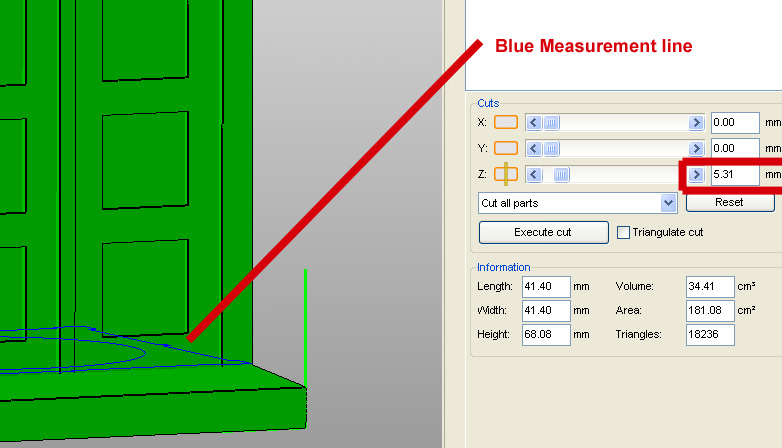
You can 'measure' a model very easily using the basic free version of Netfabb - 
This will tell you at what height the parts of the model you are interested in begin (the base line here is showing  5.31mm)

The middle section has already been hollowed out but still has quite an area that would be filled if we sliced it with 25% of infill that we need on the base. It works perfectly well with just a hollow perimeter outline.

With the different 'sets' of Gcode you have generated, you just need to open them up in an editor (I use Textpad) and search for the change in layers - G1 Z

The start of the Gcode is a handy reminder as to the settings you used - 

; generated by Slic3r 0.5.7 on 2012-00-08 at 12:09:38
; layer_height = 0.2
; perimeters = 3
; solid_layers = 3
; fill_density = 0.10
; nozzle_diameter = 0.5
; filament_diameter = 2.79
; perimeter_speed = 65
; infill_speed = 80
; travel_speed = 195
; extrusion_width_ratio = 0
; scale = 1

If you search in the Gcode for G1 Z5 


you will get to a section of Gcode like this - 

G1 F1800.000 E6.50116
G92 E0
G1 Z5.000 F11700.000
G1 X84.707 Y81.055
G1 F1800.000 E1.00000

Everything above the  G1 Z5.000  is the object up to 5mm in height, everything below is the rest of the object.

If you replace the Gcode below the G1 Z5.000 with the same objects Gcode but sliced at a different speed or infill then your object will print the original Gcode to 5mm and then the alternative Gcode after that.
You can combine Gcode however you like but for starters I recommend doing it by layer.

In Part 3 of this guide we will combine Gcode with different layer heights, this is another very handy thing when you start to print with very low layers, as you can print the first few at a 'normal height' (0.3mm) to help get a good bond to the bed and level our the surface then switch over to lower height Gcode for the rest of the object. Skeinforge has a setting in 'Skin' to do a similar job of ignoring skin on the first X layers. 


Maybe you would not go to this effort for printing one thing, but the next time you think your printing too fast, check if you can selectively slow down some layers or vary the infill of layers to both minimise print time and also maximise print quality.

So hopefully you get the idea, it's good to know more about Gcode, you can find more commands on the Reprap Wiki pages here - 

I just wanted to show one more printed object and say how it was printed, as it's a brand new test and technique for me and so far has produced some of the best results I have ever made. 

Some of my favourite things on thingiverse are the MakAlot pots and objects, but they are actually quite hard to print, especially if you print them small, you need a well calibrated machine and if you want to print them fast you run the risk of making a mess of your print or it becoming detached from the bed.

I had two prints fail by getting knocked off the bed due to a very tiny surface area (1mm) on the first layer.
they were also a little bumpy (red one on the left)

I tried to print the MakeAlot Link bracelet quite fast and both times it got knocked off the bed about 1/3 into the print, the quality was a little poor and I was about to slow-down the print when I thought this would be a perfect object to test the Z axis 'Lift' setting in Slic3r, I had not tried this before believing that the Prusa mendel Z axis would be too slow and may end up adding extra 'artefacts 'of plastic to the print, I also have my Z axis limited to 4.1mm/sec in Firmware so I was expecting worse results using 'lift'... I was so wrong.

Just using my normal settings for a standard 0.3mm layer height but also a 0.3mm 'lift' on the Z axis.
The print came off the printer as smooth as glass, I'm really impressed with the 'lift' setting, do try it!

I think that I may now be able to print this object the size of a ring, maybe a smaller nozzle would also help.

Thanks to Nophead for pointing out that the Mendel Z axis is fast enough to 'toggle' and use the 'Lift' setting. What I didn't think was that it would help produce such amazing prints, I'm going to try some more of the really complicated MakeAlot pots...


Watch it in Hi-Def Here - 

That's all for Part 2, I hope this was useful and if you do nothing else, experiment with a glass bed and the 'lift' setting.

In Part 3 we will experiment with low layer heights using Slic3r.


Thanks for reading.


Rich.