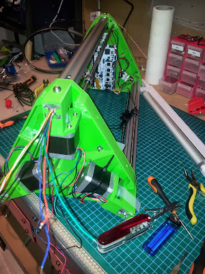
This is Part 3 of the 3DR RepRap Delta printer, in this post we will look at the final assembly and electronics, setup and wiring. Firmware, settings and calibration will be in Part 4 very soon.
Photo by Personalize - At the recent TCTShow Birmingham NEC
In Part 1 I introduced the 3DR Delta printer, the 3D printed elements and a list of the parts you would need to source, to build one yourself.
In Part 2 we looked at the preparation of parts, how the printer is assembled and stringing our Spectra Line drives.
Firstly thanks to everyone - I have had hundreds of messages and e-mails about 3DR, I'll do my best to get this build log done as soon as possible. And do keep in contact and let me know how it's going for you.
Other 3DR's are being born into the world - build progress -
The 3DR Forum thread is going really well, lots of help and advice for people building 3DR, and alternative designs starting to emerge too.
Other threads I spotted - 3DR part sourcing, Google Groups for 3DR,
Other threads to be aware of - 3DR Simple, by JohnSL - a simplified 3DR being re-designed in Solidworks.
For more model making fun check out John's blog here
Photo by - JohnSL
Photo by - JohnSL
JohnSL is doing some really cool stuff, splitting it down into even smaller parts to be printable on a PrintrBot simple.
Photo by - JohnSL
Photo by - Richard Gain
Richard Gain now has his 3DR up and running - his Blog here Richard is build a tall 3DR and also has a good break-down of costs for 3DR on his Blog.Luke Turner - Build in progress -
Photo by Luke Turner - Luke is using RAMPS electronics, so made small adapters to fit inside the top printed sections.
Photo by Luke Turner - Luke's 3DR also has some *Super-Bling* LED lighting.
Zacbot is documenting his build over here on Eventorbot.com - another very nice job, thanks!
Hannes Delago (HaDe) - 3DR build is very nice, with a really good set of photo images over on Flickr here Very nice extruder and even a Heated Bed! - I want one... :)
CidVilas - Has done a great job with a better BOM for 3DR - Google Doc Here and even created a rather nice cover for adding easier to fit electronics and a possible Raspberry Pi controller on the top rather than under. Nice!
Matt Gordon - 3DR build - almost complete now -
Photo by Matt Gordon - (Look at that Awesome MAME Cabinet :) )
Wiring with RUMBA - Photo by Matt Gordon -
Photo by - German Palacio (FraNtik) build is going together well - and also some very good photo's of this build are available here.
DeeEmm -
If you want some extra inspiration and advice on a 3DR build, do take a look at DeeEmm's build progress here
Photo by - DeeEmm also found a nice way to use hollow carbon fiber tubes for the push-rods
I'm sure there are also a lot more being built up - really nice job everyone!
Do let me know if you have built up a 3DR!
End-Stop Connections -
For the Hall end-stops you will need 3 x 3-way cables about 20cm long
For most electronic sets you will require standard 0.1" crimp housings to be fitted.
Common colour combinations are 'Red for +' 'Black for 0V (Gnd)' and 'Yellow/White for the signal'.
It's important to check you have the correct orientation and are aligned with the three pins.
End-stop wiring needs to be connected to the Positive (+) Axis connections on most electronics - note that some electronic sets only have one set of three end-stop connections.
Hot-End and Power -
If you have to build and wire up your own hot-end, do take the time to fit both the thermistor and heater well and with a solid connection, Kapton tape on it's own is NOT a good enough solution to hold things in place.
This is a standard J-head MKV from Hotends.com but I have added a small set screw to lock the cartridge heater in place and also secured the thermistor in place with fire cement.
The mount will need a little drilling after the print, you need to drill out the hole for the filament - 2mm should be fine. Then drill through the 4mm holes, insert M4 nuts and use 16mm M4 bolts+washers to secure the hot-end in place.
The Pneumatic push-fit is designed to self-tap and screw in place, if you find it's a bit tight, heat the mount with a hair-drier or heatgun, then tighten.
Secure connections and as in photo above it's also a good idea to add a 2-way cable for a fan connection to help cool the hot-end.
Thermistor connection goes to T0 on the electronics. Orientation is not important.
Hot-end connection usually goes to HE0, shown far left (Red wires) in above photo (RUMBA electronics)
A fan for cooling the printed part can be connected to one of the smaller fan outputs - black wires - shown in middle of image above.
+12V Power for the board needs to have a good sized cable, we are not using a heated bed, but still the electronics will be taking around 4A whilst running, so if you have any connectors, switches or sockets for your power input, check the rating and use suitable cable.
The fan for the hot-end is running all the time, it's purpose if to cool the cold-end insulator, you may decide not to do this or want a controlled fan on the hot-end to cool the printed part.
RUMBA provides a few spare +12V connections for things like fans and lighting - above you can see to the left of the Heater connection a small 2way 0.1" connector, this is the one I am using for cooling the hot-end.
LCD -
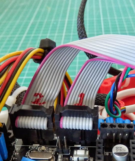
If you decide to fit an LCD (highly recommended) be aware that the RepRapdiscount connections for EXP1 and EXP2 are incorrectly labeled on RUMBA (always check this as they may decide to fix it at some point)
Make sure you have the correct orientation for the connections from the LCD, pin 1 (marked with a red cable) needs to be going to pin 1 on the RUMBA board (shown above) BUT connections from EXP1 and EXP2 from the LCD board need to be swapped over on the RUMBA end.
If you are using RAMPS or other electronics with the LCD_XL you should not need to swap EXP1/2 connections as they use an adapter directly for RAMPS connection.
Other LCD display options are also available, above is the Full graphic module.
I still always use a geared extruder for all my printers, I have found this gives the best results for me with both Bowden and direct systems. It also provides a high level of torque and fast retraction speeds.
I did plan to have hinges to help stand-off the extruder, but I dropped it from the design in the final stages of getting 3DR up and running, that was a mistake as you will need to space the extruder body away from the Aluminium frame to stop the carriage hitting the big gear.
I accidentally deleted this design after I printed a test part, it would have worked well, the 'flaps' fold around and help stand-off the extruder body away from the frame, apologies for this - I'll recreate it at some point.
Assembly requires a Hobbed Bolt and 2 x 608ZZ bearings, M8 nut, M8 washers.
Idler hinge required a section of M8 x 20mm smooth or threaded rod, and another 608ZZ bearing
Hinge springs, washers and Long M3 bolts make up the final part of the extruder body.
As with the hot-end if you have any issues fitting the Pneumatic fitting, use a little heat to soften the plastic and screw in tight.
PTFE tube should be 4mm outer and 2mm inner, you will need a section about 450mm long (for a standard sized 3DR) fitted between the two push-fit connections.
Motor connections -
The RUMBA board has two sets of connections for Motor's - if your motors have pre-wired connections you may want to keep them, but I can recommend using the screw-terminals, if you do, then also use ferrules to help clamp the wires down and avoid damage.
The use of heatsinks is advised on the Stepper drivers if you are not going to use any cooling.
It's a good idea to set each of your stepper driver current limits before running with motors attached.
In the above image the voltage reference point on a Pololu 4988 driver is marked with a red V, if you measure the voltage at this point and Ground (GND) turn the trimmer pot all the way down (counterclockwise) and turn back up clockwise until the voltage reads 0.45V you will have a current limit of around 1A.
If you are using a Stepstick driver, these are already limited to around 1A, so you will normally need to turn the trimmer pot all the way around (clockwise) - Also note that Stepstick drivers are normally fine for X,Y and Z axis, but can sometimes struggle to provide enough current for extruders, I always use a Pololu based driver for extruders to ensure you can deliver more than 1A to the extruder stepper motor if/when required.
I did make bigger fan mount for the electronics, but it was not required - I don't use a fan at all now for the electronics cooling, passive cooling seems to work fine.
Note the LCD mount has an optional mounting points for a Fan to cool the electronics, if you need it.
Another fan mount for part cooling is available on my 3DR source page, this can be really good for PLA printing things fast, like pots and small parts. Highly recommended printing at least one of them.
That's it for Part 3, I know it's a bit short, but I'm always unsure of how much to put on the electronics side as I have covered most things in my Blog before and there are so many options and choice for alternative electronics. Any questions, give me a shout.
And if you fancy a new ARM based electronics set for your next 3Dprinter/CNC project you may want to checkout the Smoothieboard Kickstarter
3DR Part 4 is half finished and will also be up soon, if you want to download the Firmware and get stuck-in, here it is on my Github page.
3D Printing food for thought -
The Open Hand Project: A Low Cost Robotic Hand
Firstly do take a look at the open Hand project running on Indiegogo - it's a great mission and they have almost reached their funding goal - Just another £9k to go as I type this. Please donate if you can.
More great stuff -
A great website with 507 mechanical movements was posted up on Google+ the other day, it's well worth a look if you want any inspiration for 3D printer design or just to see all the amazing ways to move and link things.
Did you ever wonder how to get the final hole in your hot-end? they can be very tricky to drill, take a look at this great video from Alan Long - How to drill a hot-end in 15 seconds (by hand)
And if you fancy something a little different, take a look at these Soft robots - interesting!
Thanks again everyone.
Cheers,
Rich.


