Friday, 17 December 2010

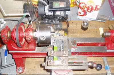
Restore of OLD Lathe for ongoing RepRapping.

So I got hold of a very old looking Metal Lathe, it had no motor or any cutting tools, but it was so cheap it was almost given away to me and it looked like fun to try and get it working again.

A few extra parts/heads (for woodworking I think?)

But it did need a Motor and some TLC before this was going to work.

Taken apart and I mounted it on some old Oak worktop along with a 1/3HP AC motor and a new belt drive. Both the motor and belt was salvaged from an old Pillar drill.

I added a Polycarbonate shield, On/Off switch along with a belt adjuster made from a spring and an M8 Bolt.

Got hold of a cheap set of 1/2" Metalworking tools and it all seems to work. Nice and stable, but I'm not sure how long the old brass bushings will last?

This is really going to help with re-construction of my RepStrap and some new hot-ends I have been working on.

If anyone knows what model or how old this would be let me know, I'm interested and would like to know more about it's origins.

Soon to be used for something cool...

Rich.


Saturday, 27 November 2010

Geared Extruder Hot-End Block finished

My new Aluminium block and resistor heater is finished and is printing very well, here is how I made it -

Drilled holes for the Brass nozzle, two resistors, one thermistor and a locking screw to keep everything tight.
Do this with a long length of Aluminium as it's much easier to clamp and work with, you can cut it down later.

I used two 3.3Ohm Resistors - Wire Wound 3W these will be wired in series- vishay-resistor-ww-3w-5-3r3

Cover them with Aluminium tape (or foil) and insert them into the Aluminium block with a little Heatsink compound if you need it - They should be a tight fit.

Then you can use some Fire Cement to hold them in and seal the ends - Bake at 200 Dec C for 15 mins.

Baked

Assembled.

Thermistor fitted into small hole and the resistors connected in series (crimped).

After a few z calibration problems with my last extruder I wanted an easy way to adjust this one, and also a quick to change it over, so this R/A Aluminium mounting plate will give me all that and some extra heat-sinking of the PTFE guide and Extruder.

Slide slots cut, so I can now easily adjust the Z height - really good for testing bed materials that may have different thickness etc.

Now to fit it all to the WADE Geared Extruder - 
All Assembled and wired up.

Done - And the first test cube printed.

Fitted to my Repstrap V1 and after a bit of calibration for the new Extruder feed-rate it's printing extremely well, and giving 100% better prints, and I also now don't need to print a shield as the tiny surface blobs I experienced with the Pinch extruder have all gone.

The Extruded filament is very smooth and consistent, and is producing great results, I'm delighted !

It's printed for about 10 hours now with this new extruder build and still working perfectly, so I can call this a success and move onto upgrading my Repstrap so I can get the print speed up...

RichRap.

Thursday, 28 October 2010

Making a new Extruder Nozzle Hot-End - DIY - using basic tools only

Due to the cold evenings it's been hard to get work done, but it was mild last night and I managed to make a new Hot-End to go with my WADE Geared Extruder, it's loosly based on Adrian's new Hot-End -http://reprap.org/wiki/Geared_extruder_nozzle
I first had a go at some heater blocks. -
On the left was an attempt to make a Clamp version, but it was a bit big and didn't clamp very well around due to the mass of Brass and the short cut slot.

In the middle was just about right, but I over-drilled the hole so tapping was not going to be good, but it was a easy part to make in the drill press and using HEX brass stock, note the small hole for the thermistor.

On the right is the Brass screws I'm going to try to make into a hot-end, normal M6 thread, and it has a nice ready-made centre point in the head.

Clamped in Vice with M6 Nuts to stop the body from getting squished.
It worked ok but the 0.5mm extruder hole ended up being 0.55mm, not a big problem, but I would not recommend doing this yourself if you don't have decent equipment, it's one good thing to buy a well made one.


Now for some support materials-
PTFE Rod 16.57mm (Ebay £0.99p for 165mm x 16mm)
PEEK Rod 14mm (Ebay £2.20 for 400mm x 16mm)
Off the shelf 16mm Aluminimum Clamp as used on my previous Pinch Extruder. (£1.50)
Clamped in Vice with level support under the PEEK then drilled with a Woodworking drill bit on the Drill press.
Repeat with the other holes in the PEEK (My spacing is to match the Aluminium clamp, and they are not the same as the mounting holes on the WADE extruder)

PTFE drilled with a 3.2mm hole and tapered (filed and sanded) to make a snug-fit into the bottom of the Extruder.

Remeber to dish the PTFE enrty hole so the filament can fint it's way into the hot-end easily.
And you need to Drill and tap (M6) a small way (I did 5mm) into the PFTE for the heater barrell, you don't need it to go a long way into the PTFE as the PEEK is doing all the support and most of the heat-sinking.


I need to make another heater block but this is about all you need.


The Aluminum clamp provides support for the PEEK and aids to mechanical fixing to the Extruder and also constrains the PTFE . It also should help with Heat-sinking.

I still don't have my Power Resistors yet; they should be here tomorrow, so with a bit of luck I can test this new Geared Extruder and Hot-End at the weekend.

I also need some longer M4 Bolts...

RichRap


Friday, 15 October 2010

New Extruder build and hobbed bolt experiments

I still have not had a chance to test my new heated bed as my extruder has been in bits for the last week.

I have been trying to make a Hobbed bolt - It's not as easy as it looks on Youtube!

My first rig used the extruder and a failed print to mount the bearings and the bolt -
Not very good, didn't turn very well.

That seems to work much better.
Hopefully that will be good enough?


When it's assembled it seems to push well, so I just need to mount the motor and work out how to strap it onto my repstrap - then completly change all my firmware again this weekend.

RichRap


Saturday, 9 October 2010

First DIY Heated-Bed build.

I had some parts on order for a Heated bed - Both the Alu Clad resistors and the Aluminium was quoted as two weeks delivery, so I used a rather scratched bit I already had to test a Heated bed.


MDF base, then a layer of Aluminium Foil (not shown)
Opal Polycarbonate 3mm sheet.
Silicone baking sheet (240 deg rated)
Then 3mm Aluminium sheet.

And because of not having my Resistors, I didn't want to use Nichrome Wire, so I went for a quick and dirty method others seem to have had some success with...

A brand new Iron for just £3.84 (1/4 the price of my resistor order) - It was also a good plan getting the cheapest Iron, as this just had a very thin Stainless sheet over a nice cast Aluminium base, and it was very small and Light -
So Rip-off the Stainless sheet, and remove the red silicone blob.

It has 3 mounting points already, they just need to be drilled through.
Sand the base with fine wet and dry.
Add a fine layer of heatsink compound and fix to Aluminium plate.
Wire it up and isolate.

Assembled and a glass hot-plate (£1.50) on top, this should be good for PLA (not tested yet).

For PLA It's getting 55 deg C-in the middle and about 50 deg C around the edges, may need a little more tweaking.

Without the glass and at maximum power I can get it up to 130deg C (120 edge) so it should just about be ok for ABS? - Hopefully I can test it tomorrow.

The MDF only gets slightly warm so it seems to be a reasonable use of materials, I would have liked to use PTFE Sheet, but maybe on the next one.

The very next day my Aluminium order turned up, so at least I can build a really nice one for the next machine...

Still waiting for my resistors to get here, but I'm really happy with the Iron for now.

RichRap

Tuesday, 28 September 2010

WADE Extruder parts printed - And My UP! Bearing finished

They all printed well, just a very small warp in the big part, and it messed up the last top layer for some reason?

The big Cog is perfectly flat, I can't really understand why, I was expecting major warp on that.

I am using 2 layers of Kapton tape at 90degrees, I think it's making my prints stick-down better.

I now need to make the hobbed bolt and assemble it then re-calibrate my whole machine again.

I have also started on a Heated build-bed so as soon as I get both working I can start to print my parts for mendel.

I also forgot to mention that I re-started my UP! Bearing print (by hacking the first 27 layers out of the GCode), it finished and the bearing worked !  I'm still amazed that it all fused together especially after a long gap between printing the first half and the second.
See the blue line -


And it rotated 180 degrees.

This is full-size, I did try a another at 50% size but that didn't work very well.

It's printing the Stanford Bunny at the moment to celebrate getting my extruder parts made.
- Bunny - http://www.thingiverse.com/thing:3731 -check it out, a great model.

RichRap

Monday, 27 September 2010

Printing Upgrades - Progress update

I have not had much time to print or experiment with my Repstrap in the last week, but it has been hard at work printing my first Geared Extruder parts so it can start to upgrade itself.

Tweaking and tuning for better Quality has been very worthwhile, it teaches you lots about Fused-filament limits and also about you'r specific system, you can't learn everything from a Wiki, Forum or Blogs, the best method is try it yourself.
For now I have settled on the following settings so I can start to print out some practical upgrade parts.
This is not the best quality, but I'm getting minimal warp and speed is not bad - 
A print speed of 1000mm / min
0.4 layer height
0.5 Nozzle size (but I'm going to make and test a 0.7 shortly)
One outer shell (2 shells when printing gears)
1.5mm Infill pattern (45 and -45)
Outline at 90% speed.
Basic Pinch-wheel Extruder (That I'm very impressed with actually)

Still not using accelerations in my firmware, but as soon as I have a working Geared extruder, then I'm going to re-tune the whole system again and switch Accelerations back on to try getting the speed up.

Print 1 on the far left was the very first thing my machine printed.

Print 2 was 1.8mm infill and slow, ok quality, but not correct Extruder settings.

Print 3 was much too fast. Good extruder settings, but the motor was skipping steps (you can see loops of infill at the front).

Print 4 has just completed, 1000mm/min 1 outline and 1.5mm Infill, nice and smooth, and feels strong.

I printed a few other things, to test some of the earlier settings - 
Whistle - (Version 2) - http://www.thingiverse.com/thing:1046

Probe Holder - (only 50% printed, I decided I didn't need one that badly) - http://www.thingiverse.com/thing:3525

It's printing the Geared Extruder Block and both the WADE gears Now, so I will hopefully be able to Blog them tomorrow.

RichRap.


Wednesday, 22 September 2010

How I made my Basic Extruder -

I Just thought  I would put up a few photos showing my first basic extruder, it's working very well and I have used off-the shelf Aluminium 16mm clamps -

You can get these from many places for just a few pounds each (£1.50, $2, 2Euro).

These both hold it to my Repstrap frame and also constrain the PEEK/PTFE hot-end.

It also has the added advantage of cooling the hot-end PEEK, so less of the heat travels up towards the extruder - all good things.


It's just a basic Pinch at the moment, I plan to print a Geared Extruder over the next few days and use the same 16mm Aluminium mounts on that.

RichRap.

Monday, 20 September 2010

Warp Factor 9! - Printing the PP3DP (UP!) Bearing on My Repstrap

So maybe a bit over ambitious for a Repstrap with no Heated bed but I had a go anyway.

I really like the UP! Bearing - get it here - http://www.thingiverse.com/thing:3981


Not a bad start - Poor choice of infill size - too many start-stop operations
Starting to warp on the front edge - Note my use of double sided tape! in a poor attempt to counter the warp.
At this point the warp was going to destroy my extruder, so I reluctantly had to turn it off. You can see the bottom front edge getting more and more melted after each pass.

It would have taken about 2 hours 20mins to print in total, which is almost exactly twice as long as on the Up! Printer, I expect it could have be much faster as I had it set on 2 x Shells and a slow outline speed. it was also resetting to origin after every layer.

All the bearings are clear and I think would have moved and worked if I could have printed it all.


If anyone has a Mendel with a heated bed, I would love to see if this could be printed and if it worked afterwards. - Let me know...


If you want to try - You will need a support structure;  -
I made a 1.7mm high ring positioned under the balls to get them to the correct height in the bearing. For me the balls started to print after layer 4. The ring needs to be 58mm outer and 46mm inner. - Good Luck !


I really need to stop messing about and print some upgrades for my extruder, but it was lots of fun trying to print this.

I really want a heated build-bed now...

RichRap.

Sunday, 19 September 2010

Compare the frog

I was getting bored of printing test cubes, so I spotted a small frog that looked like it would be an interesting challenge to test quality, and sure enough I discovered something...

Test frog from here - Frog by Owenscenic - it's the little one test frog.stl (there is also a big one, I may try later)

So I printed the first frog (placed in the top right in the photo below) and he had quite a lot of brown bobbles on his left hand side (the side closest to machine 0 - origin).
So on the next test print I re-enabled the shield option (frog on the bottom left) You can see that the shield wipes off the spare ABS and stops brown bobbles, it also seems to make less string-bits and gives a better overall end result.
Compare the Frog ! - Left with wiper-shield and Right without.


Prints are sticking really well now to the Kapton tape. - but I may have problems when I try to print larger parts.

Some close-ups for a review of Quality -

This is the underside of the above frog, nice and glass-shiny, and the next layer looks well fixed to the base.


This is a close-up of infill using a 0.8mm infill gap, looks quite a nice uniform hatch.

This is infill with a 1.5mm spacing, slightly more sag.

Overall I'm very happy with my basic pinch-wheel extruder, I didn't think it would be very good and I expected to be wanting to print a geared replacement ASAP, but at the moment I'm having too much fun printing other stuff, mind you a big gear would also be a good test...

On with printing -

RichRap